The fixing system is the mechanical interface between the solar array and the building structure. It is the component that must transfer wind uplift, dead load, and maintenance access loads from the array into the structural frame without failure. For commercial rooftop solar, the choice and design of fixing systems is a structural engineering decision, not a product selection decision, and it must be documented and signed off by a structural engineer.
This article covers the four primary fixing system types used in commercial rooftop solar, the structural calculations required for each, and the failure modes that correct structural assessment prevents.
The Four Primary Fixing System Types
1. Through-fix to purlin: The mounting rail or foot plate is fixed directly through the roof sheeting into the structural purlin below. This is the highest-integrity fixing method, the structural element directly carries the load without relying on the deck alone. Through-fix to purlin is suitable for any wind uplift zone and is the preferred option where structural capacity allows. It requires accurate knowledge of purlin locations and adequate purlin section for the fixing pattern.
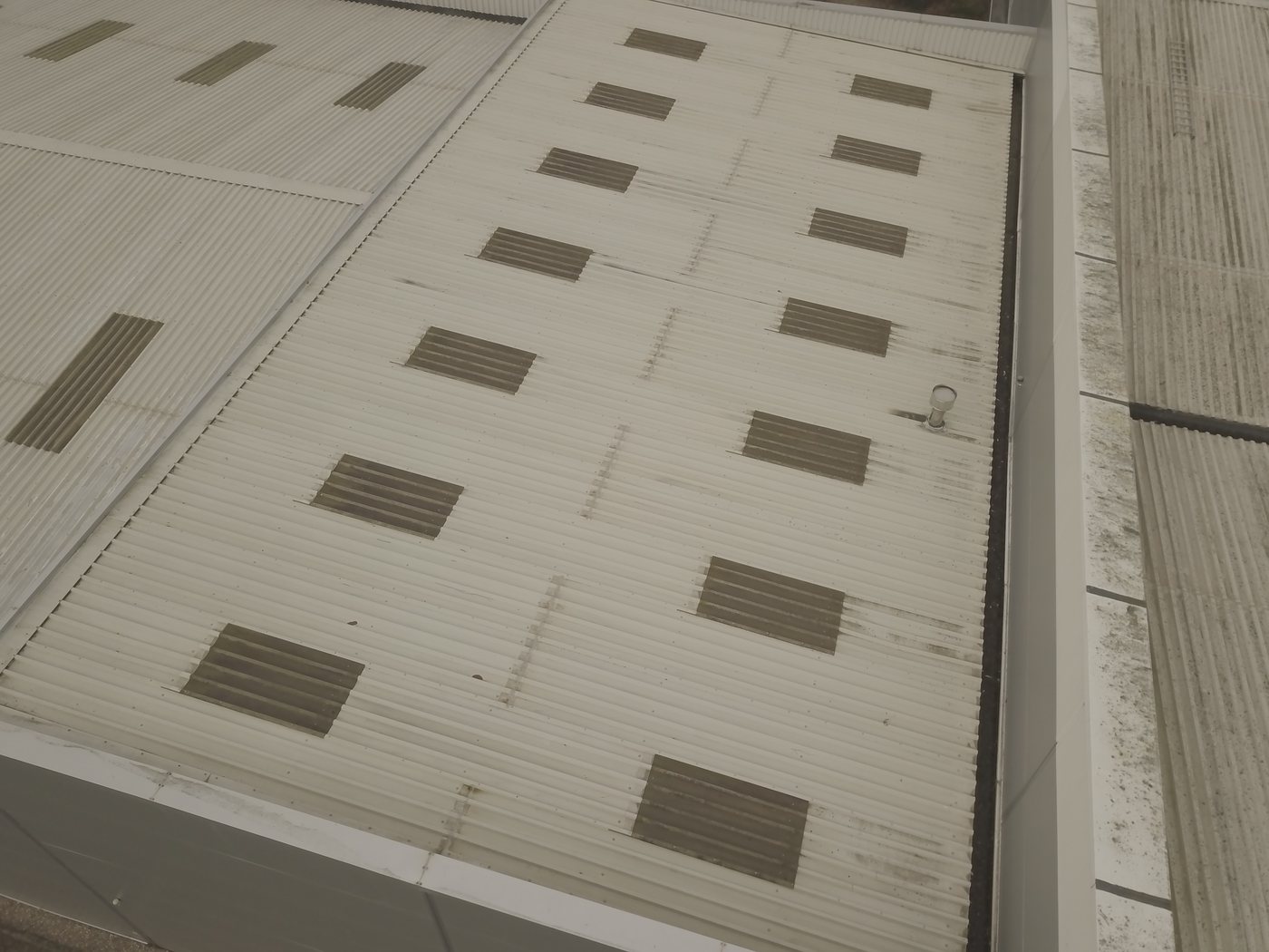
2. Seam clamp (standing seam roofs): For profiled metal roofs with standing seams, clamps grip the raised seam without penetrating the membrane. Seam clamps have high pull-out resistance (typically tested by the manufacturer to 3-5 kN per clamp) and do not require roof penetrations. They are only applicable to standing seam profiles, they cannot be used on trapezoidal or sinusoidal profiles without a standing seam. Structural assessment must verify that the seam itself, and the purlin connection below, has adequate capacity for the clamping force and the uplift load it transfers.
3. Ballast-only (flat roofs): No mechanical fixings to the structural deck; the array is held down by the weight of concrete ballast blocks. Dead load: 20-30 kg/m². Ballast-only systems avoid membrane penetrations and are suitable for inverted or protected membrane roofs. Structural assessment must verify that the roof structure can carry the ballast dead load in all areas, including edge and corner zones where additional ballast is typically required.
4. Adhesive bonding systems: Specialised adhesive systems bond mounting feet directly to the roof membrane without penetrations. Used on membrane roofs where ballast loads exceed structural capacity and mechanical fixings would compromise the membrane. Structural assessment must verify that the adhesive bond strength (confirmed by manufacturer pull-off testing on the specific membrane type) is adequate for the site-specific wind uplift forces. Adhesive systems have more installation and inspection requirements than mechanical fixing, quality control is critical.
Fixing Adequacy Calculations
For any mechanical fixing system, the structural engineer must calculate the design pull-out force at the fixing and verify that the fixing capacity, the resistance of the fixing in both pull-out (tensile) and shear, exceeds the design load with an appropriate factor of safety.
Pull-out testing measures the actual resistance of a proposed fixing installed in the actual substrate at the actual site. A hydraulic test rig pulls the fixing vertically until failure or to a specified test load. The test load is typically 1.5× the design load, with a pass/fail criterion. Pull-out testing is required when: manufacturer load tables do not cover the specific substrate; the substrate is non-standard or has degraded; the fixing pattern departs from standard spacing; or the structural engineer cannot verify substrate properties from drawings. For commercial solar on pre-1990 buildings, pull-out testing is frequently required because the deck gauge and material properties cannot be confirmed from available drawings.
The calculation chain for through-fixing is:
- Calculate design wind uplift at each fixing location using BS EN 1991-1-4 NA (zone-specific)
- Determine the number of fixings per panel / per bay and the load share per fixing
- Check fixing capacity from manufacturer data (or pull-out test results): fixing must carry design load with a factor of safety of at least 1.5 for characteristic resistance
- Check the substrate (deck or purlin) for local bearing failure or pull-through
- Check the structural element below the fixing point for global capacity under the imposed load
Fixing Design at Roof Edge and Corner Zones
Wind uplift pressures in edge and corner zones of flat and low-pitched roofs (BS EN 1991-1-4 NA zones F, G, H) are significantly higher than in internal zones. A fixing pattern designed for internal zone loads will be inadequate in edge and corner positions. The fixing design must address each zone explicitly:
- Internal zones (H): Standard fixing pattern, typically 4-6 fixings per panel
- Edge zones (F, G): Increased fixing density or ballast, or both. May require additional purlin check where fixings are concentrated
- Corner zones: Highest uplift zone, may require fixing pattern that cannot be achieved with standard mounting hardware. Sometimes the solution is to set the array back from the roof edge to avoid the corner zone entirely.
Seam Clamp Structural Verification
Standing seam clamps grip the raised seam of the roof profile. The structural chain is: wind uplift → clamp → seam → purlin-to-seam connection → purlin → primary frame. Each link in this chain must be verified:
Clamp-to-seam bond: Manufacturer provides characteristic resistance values (kN per clamp). These values are profile-specific, a clamp rated for one seam profile may have significantly different performance on another.
Seam-to-purlin connection: The seam is formed from profiled sheeting fixed to the purlin. The fixing that attaches the sheeting to the purlin must be adequate to transfer the clamp load into the purlin without pulling through the sheeting.
Purlin adequacy: The purlin must carry the transferred clamping forces in addition to existing loads. For light-gauge cold-formed purlins (Zed or Sigma sections), this requires section capacity check to BS EN 1993-1-3.
Installation Quality Control and Structural Sign-Off
The structural sign-off for a fixing system is conditional on correct installation. A calculation showing that a specified fixing pattern is adequate is not a guarantee that the as-installed system is adequate, installation quality control is required to close the gap.
Structural sign-off documents for commercial solar installations should include conditions on installation: specified torque values for threaded fixings, inspection requirements for pull-out samples, and post-installation inspection requirements. Where the installer deviates from the specified fixing pattern during installation, the structural engineer must be notified before the installation is completed, not after.
Warranty and Long-Term Considerations
Fixing systems are the component most exposed to long-term degradation in a solar installation. Bimetallic corrosion (dissimilar metals in contact), inadequate coatings on fixings through membrane penetrations, and thermal cycling fatigue in clamp-to-seam connections are all long-term failure risks that a structural assessment should address.
For a 25-year system life, the structural engineer should specify:
- Fixing material specification appropriate to the exposure category (A4 stainless steel for coastal or humid environments)
- Isolation between dissimilar metals where applicable
- Inspection intervals for fixing integrity checks
- Replacement criteria if fixing degradation is detected
These requirements, included in the structural sign-off documentation, form part of the operations and maintenance specification for the installation and should be passed to the asset manager at practical completion.
Fixing System Documentation for Asset Handover
The fixing system documentation produced at installation forms a critical part of the asset handover package. Future owners, insurers, and lenders need to know not just that the system was structurally cleared but precisely how it was fixed, which fixing type, at what pattern, and with what specified capacity. This information allows future structural assessments (at refinancing, at panel replacement, or following a structural incident) to be conducted accurately.
A complete fixing system documentation package for handover includes:
- Fixing system specification: manufacturer, product reference, material grade, corrosion protection specification
- Fixing pattern drawing: plan view of the roof showing fixing locations by zone, with zone-specific fixing spacings noted
- Pull-out test results (where conducted): test records showing fixings tested, test locations on the roof, applied test loads, and pass/fail outcomes
- Torque records: confirmation that threaded fixings were installed to the specified torque value
- Structural sign-off letter: the structural engineer's clearance, which references the fixing system and pattern described above
This documentation should be filed in the project record alongside the structural assessment report, not on a separate system where it may be separated from the report it references.
Fixing System Inspection During the Operational Period
Fixing systems degrade over time through corrosion, fatigue, and thermal cycling. An inspection programme for fixing integrity during the operational period is good practice for any commercial solar installation and is increasingly a condition of institutional insurance and lender requirements.
A robust fixing inspection programme includes:
- Annual visual inspection: Check a representative sample of fixings for visible corrosion, movement, or damage. Any abnormalities trigger a more detailed inspection. Visual inspection can be conducted by a trained technician, not necessarily a structural engineer.
- Five-yearly torque check: A sample of threaded fixings re-torqued to the specified torque value and checked for under-torque (indicating relaxation or corrosion-induced loosening). Conducted by the installer or a structural inspection specialist.
- Post-event inspection: Following any significant weather event (wind gusts exceeding the design speed), structural inspection of fixings in the most-affected zones, typically edge and corner areas. Any displaced panels, unseated clamps, or pulled-through fixings require immediate rectification and a structural review before the system is returned to full operation.
Specification Verification at Installation
The structural assessment approves a specific fixing system, installed in a specific pattern. The as-installed fixing system must match this specification, any deviation is a potential structural non-compliance that could invalidate the sign-off. Specification verification at installation requires:
- A hold point during installation where the structural engineer (or their representative) inspects the fixing pattern before additional work covers it
- Confirmation of fixing type and product reference, not just that fixings were installed, but that the specified product was used
- Random torque checks during installation, the installer tightening fixings to feel rather than to a calibrated torque wrench is not adequate quality control for a 25-year structural commitment
- Documentation of any deviations from the approved pattern, with notification to the structural engineer and approval of any alternative
For large commercial installations with hundreds or thousands of individual fixings, 100% inspection is not feasible. A statistically meaningful sampling regime, one that gives reasonable confidence that the full population of fixings meets specification, is the realistic minimum. The structural engineer should specify the inspection regime proportionate to the risk level of the installation.
Corrosion Resistance and Fixing Material Specification
The long-term structural integrity of a rooftop PV installation depends not only on the initial load-carrying capacity of the fixings but on their resistance to corrosion over the 25-40-year design life of the array. Corrosion of roof fixings, particularly in coastal, industrial, or polluted environments, is one of the most common causes of PV racking failure on commercial buildings, and the structural assessment must confirm that the specified fixing materials are appropriate for the site’s environmental exposure category.
BS EN ISO 12944 defines corrosion categories for industrial and building environments ranging from C1 (very low, dry indoor) to C5-I and C5-M (very high, industrial and marine). For most UK commercial rooftop solar installations, the applicable corrosion category for exposed fixings on the roof surface is C3 (medium, urban industrial atmosphere) to C4 (high, industrial areas with moderate humidity and some pollution). Coastal sites within approximately 10km of the sea, or sites adjacent to chemical processing facilities, may fall into the C5 category, requiring fixing materials with significantly enhanced corrosion resistance.
Standard structural steelwork fixings, hot-dip galvanised (HDG) M12 bolts and self-drilling screws, provide adequate corrosion resistance in C3 exposure conditions. In C4 environments, stainless steel (A2-70 or A4-80 grade) fixings are the standard specification for through-fixed racking systems. In C5 environments, A4-316 grade stainless steel or Duplex 2205 fixings with appropriate surface treatment are required to achieve the expected design life. Using standard HDG fixings on a coastal site where stainless steel is required represents a design deficiency that the structural engineer should identify and flag in the fixing specification section of the structural report.
For ballasted racking systems, the fixing material specification applies to the racking-to-panel connections and any restraint fixings rather than to the primary ballast attachment. Ballasted systems that rely entirely on self-weight for wind uplift resistance do not have through-penetrating fixings and therefore do not have the same corrosion risk at the roof interface. However, the racking aluminium and stainless steel connections within the racking frame itself should be confirmed as compatible with each other, dissimilar metal contact between aluminium and carbon steel in a wet environment accelerates galvanic corrosion of the aluminium, and all racking component connections should use compatible metal grades or appropriately isolating inserts.
Installation Torque, Pull-Out Capacity, and Quality Assurance
The structural assessment calculates the required fixing capacity based on the design loads, but the actual fixing performance depends on the installation being executed correctly, correct pilot hole diameter, correct installation torque, correct embedment depth in composite profiles, and confirmation that the fixing has achieved its design capacity without over-driving or stripping. Quality assurance for structural fixings is a distinct scope item from the structural assessment, and its absence from the installation record is a latent risk that can affect insurance claims and warranty positions.
Self-drilling screws into metal profiled sheeting and supporting purlins require installation to specific torque limits. Under-torquing leaves the fixing loose in the purlin flange, reducing the effective bearing area and the pull-out capacity. Over-torquing strips the screw thread in the thin metal of the purlin flange, completely eliminating pull-out resistance. The correct installation torque range is specified by the fixing manufacturer and should be confirmed in the racking installer’s method statement, with torque wrench calibration records available for inspection.
Mechanical pull-out testing, physically testing a sample of installed fixings to confirm they achieve the design pull-out load without failure, is the most reliable quality assurance method for structural fixings on high-consequence installations. It is not universally required on all commercial solar projects, but it is standard practice on projects where the structural clearance included specific fixing requirements, where the roof material has been assessed as potentially variable in condition (corrosion, manufacturing variation in thin gauge material), or where the lender or insurer requires third-party QA evidence of fixing performance. The structural engineer should specify in the report whether pull-out testing is recommended, and if so, what the minimum design pull-out load is and what sampling frequency should be applied.
Fixing Systems for Non-Standard Roof Substrates
Standard through-fixing methodology assumes a roof construction of metal profile sheeting over cold-formed steel purlins, the dominant construction form for UK industrial buildings. Where the roof substrate differs from this standard, the fixing system must be adapted accordingly, and the structural assessment must address the specific fixing options available for the substrate type.
Concrete or fibre-reinforced concrete (FRC) flat roofs require different fixing approaches from metal-over-purlin systems. Mechanically fixed ballasted racking on concrete decks may use chemical anchors or concrete screw anchors (Torkon type) engaging directly with the structural concrete. The pull-out capacity of anchors in concrete depends on concrete compressive strength, anchor embedment depth, edge distances, and the condition of the concrete at the anchor location. Where concrete compressive strength is unknown, pull-out testing on a sample of installed anchors is the most reliable method of confirming design capacity before the full array is installed.
Timber-framed roofs, common in older commercial and agricultural buildings, use structural screws or coach bolts engaging with rafters or purlin timber. The design pull-out capacity of screws in timber depends on the timber species, moisture content, and screw thread engagement length. Structural screws specified under ETA-approved fixings (European Technical Assessment for timber connections) provide defined characteristic pull-out values that the structural engineer can use in design calculations. Generic screws without an ETA may have unknown pull-out characteristics and should not be used for structural fixing of PV racking without testing or conservative capacity reduction factors.
The three primary fixing systems for commercial rooftop solar create three distinct load paths: direct-fix to purlin or rafter (highest structural efficiency, requires purlin location confirmation); clamp-to-standing-seam (no penetration, load distributed along seam length, dependent on seam geometry and material specification); and ballasted free-standing (no structural penetration, load through roof membrane to structure, membrane capacity governs). The structural assessment methodology differs for each. The fixing system must be confirmed at instruction for the structural report to address the correct load path.
WHERE SOLAR SURVEYS ADDS VALUE
FIXING SYSTEM STRUCTURAL ASSESSMENT, SUBSTRATE-SPECIFIC SPECIFICATION
Solar Surveys assesses fixing system adequacy as an integral part of every desktop structural report, not as a separate scope item. Wind uplift forces are calculated per BRE Digest 489 with site-specific wind speed, and the required fixing capacity per attachment point is confirmed against the specified fixing type and substrate. Edge zone fixing enhancement specifications are stated explicitly where required. Fixing material corrosion category recommendations are included for coastal and industrial sites. Reports are complete on delivery, no supplementary fixing specification required.
CLIENT PROFILE
A coastal distribution warehouse in a C5-M corrosion environment had been specified with hot-dip galvanised fixings by the racking supplier, whose standard specification did not account for the marine atmosphere. The structural report identified the corrosion category and specified A4-316 stainless steel fixings as the minimum requirement for the 25-year design life. The racking supplier revised their fixing specification accordingly. Five years post-installation, a routine drone inspection of the roof showed no fixing corrosion, confirming that the material upgrade had been necessary and effective.
THE STRUCTURAL TRINITY
Three Reports That Clear a Commercial Solar Site for Installation
READY TO COMMISSION
Get a Quote in 24 Hours.
Structural surveys, Desktop Structural Roof Loading Reports, drone assessments and solar design packages, delivered to a 48-hour benchmark.
Get a Quote