When a structural engineer reviews a commercial building for rooftop solar PV sign-off, three distinct calculation sets must be completed, documented, and defensible before a clearance verdict can be issued: dead load capacity, wind uplift resistance, and snow loading (where applicable). Each is a standalone engineering check. Each can be the limiting constraint that determines whether a building gets unconditional clearance, conditional clearance, or a referral for further investigation.
This article explains what each check involves, what the typical numerical outputs look like, and what site or building conditions are most likely to generate a conditional or adverse result.
Why Structural Calculations Matter
A rooftop PV array modifies the load environment of a roof structure in three ways. It adds dead load, the self-weight of the panels, racking, and fixings applied to the purlins or rafters. It changes the wind load distribution across the roof, creating zones of high net uplift at array edges and corners that differ from the original wind load design basis. And it can alter snow accumulation patterns, creating drift loads in and around the array that differ from the design snow load assumed when the building was constructed.
For most standard UK commercial industrial buildings, steel portal frame warehouses, distribution units, light manufacturing facilities, the additional loads from a standard crystalline silicon array are within the residual structural capacity of the building. But the calculations exist to confirm this, not assume it. Assuming adequacy on the basis that the building “looks fine” is not engineering, it is risk transfer to the installer, the developer, and ultimately the building owner.
Dead Load Assessment
The dead load of a conventional crystalline silicon PV array with standard aluminium portrait-mounting racking is typically in the range of 0.12 kN/m² to 0.18 kN/m² for glass-backsheet panels. Bifacial glass-glass panels with more substantial racking can approach 0.22 kN/m² to 0.25 kN/m². These loads are applied over the tributary area of each purlin or rafter that supports the racking system.
The bending stress calculation for a uniformly loaded simply supported purlin:
M = (w × L²) / 8 | σ = M / Z | Check: σ ≤ py / γM0
Where w is the combined dead load per unit length (existing roof dead load plus PV array dead load, multiplied by the tributary width), L is the purlin span, Z is the elastic section modulus of the purlin section, py is the design strength of the steel (275 N/mm² for S275, 355 N/mm² for S355), and γM0 = 1.0 per EN 1993-1-1.
The serviceability deflection check: δ = (5 × ws × L&sup4;) / (384 × E × I), compared to span/200 for roofing elements.
For most standard Z or C section purlins of 200mm-300mm depth and 1.5mm-2.5mm gauge in typical UK commercial construction, there is sufficient residual capacity to carry a conventional lightweight PV array. The cases where the dead load check becomes the limiting constraint are:
- Purlins that are already near full capacity under the existing design loading
- Long-span purlins (greater than 1.8m centres) where the tributary area per purlin is high
- Lightweight gauge purlins (less than 1.5mm) common in some post-1990 cost-optimised industrial buildings
- Glass-glass bifacial panels where array dead load is at the upper end of the range
- Buildings where section loss from corrosion has reduced the effective section modulus below the nominal value
Wind Uplift Analysis
Wind uplift is typically the critical load case for rooftop solar arrays in the UK. The array presents an inclined surface exposed to wind loading, and the net effect, the combination of pressure on the upper surface and suction on the lower surface, generates significant uplift forces that must be transferred through the fixing system into the host structure.
The wind pressure calculation follows the UK National Annex to EN 1991-1-4:
vb = cdir × cseason × vb,0 | qp(z) = [1 + 7 × Iv(z)] × 0.5 × ρ × vm²(z)
Where vb,0 is the fundamental basic wind velocity for the site location from the national wind speed map (typically 21 m/s to 30 m/s across UK sites), cdir and cseason are the direction and season factors, vm(z) is the mean wind velocity at height z accounting for terrain roughness and orography, Iv(z) is the turbulence intensity, and ρ is air density (1.25 kg/m³).
Array-specific net pressure coefficients cp,net are taken from BRE Digest 489, which provides coefficients for PV arrays on flat and pitched roofs at varying tilt angles and array positions. Typical values for a 15° tilt array on a flat industrial roof:
- Field panels (interior of array): cp,net ≈ −0.8 (net uplift)
- Edge row panels: cp,net ≈ −1.5 to −2.0
- Corner panels: cp,net ≈ −2.5 to −3.0
This is why perimeter rows of a PV array require higher fixing density than field panels, and why a single fixing specification applied uniformly across an array is likely to under-specify fixings at the most exposed positions.
The design uplift force per fixing (Fd) is compared to the design fixing resistance. For screw fixings into cold-formed steel Z-purlin flanges, the pull-out resistance per EN 1993-1-3 is approximately 3.0-4.5 kN per fixing depending on screw diameter, purlin gauge, and steel grade. Where Fd exceeds the single-fixing resistance at edge positions, the options are: reduce fixing spacing (more fixings per panel), upgrade to larger-diameter screws, or restrict the maximum array tilt angle.
Snow Loading
For UK locations above 100m ordnance datum, which includes significant proportions of Scotland, Wales, Northern England, and the Pennines, snow loading is assessed as a co-dominant load case alongside wind uplift.
The characteristic snow load on the ground sk is taken from the UK national snow load map (EN 1991-1-3 Figure A.1 as modified by the UK National Annex). This is converted to a roof snow load using the shape coefficient µi = 0.8 for flat-to-shallow-pitched roofs.
For PV arrays, snow drift accumulation behind and beneath the array must be included. Panels at less than 5° from horizontal retain snow until it melts; panels at 15° or more will generally shed snow. Snow piled against the lower edge of an inclined array creates a localised drift load that can exceed the general roof snow load and must be checked against the purlin capacity.
What Triggers a Conditional Clearance
Conditional clearance is the correct verdict when the structure is adequate provided specific installation constraints are observed. Common conditions in commercial solar structural reports:
- Maximum panel dead load per m²: triggered where the purlin capacity check shows limited headroom; the condition specifies that panels must not exceed a defined dead load per unit area.
- Minimum fixing frequency at array perimeter: triggered where the wind uplift check shows edge and corner uplift demands that require higher fixing density than the field panels.
- Exclusion zones: areas of the roof identified from condition data as structurally compromised, subject to drainage issues, or with existing penetrations that conflict with racking layout.
- Maximum array tilt angle: triggered at exposed or high-wind-speed sites where wind uplift at higher tilt angles exceeds the fixing capacity.
- Pre-installation remediation to identified purlins: where specific sections are assessed as below the required capacity and strengthening or replacement is required before structural clearance can be confirmed.
Conditional clearance is not a failed result. It is an accurate engineering result that defines the parameters within which the installation can proceed safely. An unconditional clearance on a building that genuinely has constraints is a worse outcome than a conditional clearance that correctly identifies and documents those constraints.
The structural calculations for a rooftop PV array are not an administrative hurdle. They are the engineering basis on which the installation is designed, the fixings are specified, and the long-term structural integrity of the building and the array is assured.
Worked Example: Z-Purlin at 1,800mm Centres Under PV Dead Load
A concrete scenario illustrates how purlin capacity calculations operate in practice. A warehouse built in the late 1980s carries cold-formed Z250 purlins at 1,800mm centres spanning 6.5m between primary portal frame rafters. The original design was completed to BS 5950 Part 5, which is the superseded code but remains the reference for assessing what capacity the structure was designed to carry. The proposed PV array uses 430W crystalline silicon panels in portrait racking configuration, generating an estimated distributed dead load of 0.18 kN/m² inclusive of panels, racking, and fixings.
The desktop structural report first establishes the existing design capacity of the purlin under original loading assumptions. Manufacturer load tables for a Z250 section at 6.5m span, with a standard 15% load-sharing factor applied where anti-sag rods are present, give a maximum uniformly distributed load of approximately 2.8 kN/m. This corresponds to a distributed area load capacity of 0.44 kN/m² across the 1,800mm tributary width before any existing roof loads are deducted.
With a typical built-up roof assembly dead load of 0.12 kN/m² (insulated metal cladding with liner and spacer system), the residual capacity available for additional loads is approximately 0.32 kN/m². The proposed PV array at 0.18 kN/m² falls within this envelope with a margin of 0.14 kN/m². This result would support unconditional clearance on dead load grounds, subject to the wind uplift check being separately satisfied. This scenario represents the majority of UK portal frame industrial buildings constructed between 1985 and 2010. The worked example shows why most standard assessments reach a straightforward clearance decision: the PV load is typically a fraction of the residual structural capacity available.
Snow Load Accumulation Behind PV Arrays: When Altitude Changes the Outcome
For most UK sites at low elevation, snow loading is not the controlling structural check for rooftop PV installation. The UK characteristic ground snow load is typically 0.5-0.6 kN/m² at sea level, and for pitched roofs above 20° the slope coefficient in BS EN 1991-1-3 and its UK National Annex reduces the roof snow load significantly. At a 15° pitched metal roof, the basic undrifted snow load is approximately 0.4 kN/m², manageable within standard portal frame capacity.
However, PV arrays alter the snow accumulation regime in two ways. First, the raised profile of a portrait-mounted array creates a downwind trap that accumulates drifted snow between rows and at the array downslope edge. BS EN 1991-1-3 Section 5 addresses exceptional and drifted snow loading, but its application to PV racking configurations is not explicitly codified, the structural engineer must apply engineering judgment about whether a shaped drift load applies to the purlin spans affected by array geometry.
Second, altitude has a material effect on ground snow load that is directly relevant to large portions of the UK solar estate. Sites above 100m altitude, covering significant parts of Scotland, Wales, Northern England, and the Midlands, attract a characteristic ground snow load substantially higher than sea-level values. At 300m altitude a site with a sea-level sk of 0.5 kN/m² may carry a design roof snow load exceeding 1.0 kN/m² after applying the altitude correction factor and relevant drift coefficients. Where this applies, snow loading becomes the controlling constraint on purlin capacity, and the desktop structural report will identify it as such.
The practical implication: on any site above 200m altitude, provide the structural engineer with the proposed racking configuration including row spacing and panel tilt angle at instruction stage. Row spacing and tilt affect the potential drift trap geometry and therefore the shaped snow load magnitude, a detail that can move a borderline result from conditional to unconditional clearance, or trigger a referral to on-site investigation.
Interpreting a Conditional Result: What It Means in Practice
A conditional structural clearance is not a rejection. It is an engineering statement that installation is viable subject to specific constraints, which the installer must satisfy in their design. Understanding what the condition actually requires is essential to avoid unnecessary delays or design revisions.
The most common condition on purlin capacity checks is a maximum dead load constraint: the report will state something such as “structural clearance is granted subject to PV array dead load not exceeding 0.22 kN/m² inclusive of all racking, panels, and fixings”. This is a design parameter that the racking supplier can work to, most standard aluminium racking systems with crystalline silicon panels fall in the 0.14-0.22 kN/m² range, so a constraint at 0.22 kN/m² typically does not require any change to the specification. The installer confirms with the racking supplier that their system meets the limit, records this in the project file, and proceeds.
A second common condition relates to fixing density at wind uplift zones: “edge zone fixing centres to comply with wind load analysis appended to this report”. This requires the racking installer to follow a specific fixing pattern at the perimeter of the array rather than a uniform centre-to-centre spacing. This is a racking design instruction, not a structural objection.
Where the condition requires a structural upgrade, additional purlin bridging, replacement of specific purlin sections, or bolted connections to primary structure, the report will specify the nature of the upgrade and the standard it must be completed to. These cases are minority outcomes but represent a clear engineering scope that a structural contractor can price and deliver. The desktop report in these cases functions as a pre-consent structural specification rather than a barrier to development.
Documentation Requirements for Structural Calculations
The calculation outputs from a desktop structural assessment are not simply internal working documents, they form part of a professional record that may be reviewed by third parties including MCS Scheme Providers, lender technical advisors, and building insurers. The expectation from each of these audiences is that calculations are site-specific, reference the applicable standards and their UK National Annexes, and are checked and signed by a qualified Structural Engineer before being issued.
Site-specific means that wind speed has been determined from the specific OS grid reference using the BS EN 1991-1-4 UK National Annex procedure, not a generalised regional assumption. Snow load has been checked against the relevant ground snow load for the site location and altitude. Purlin capacity has been verified against the actual section size identified for the building, not a standard section assumed from a typical specification. Where drawings were not available and measurements were taken in the field or inferred from aerial imagery, this is stated in the methodology section with appropriate caveats on accuracy.
This level of documentation specificity is a professional standard, not an optional premium. Reports that rely on generic regional assumptions or fail to confirm the basis of their input data are inadequate for MCS certification and routinely queried by LTAs. Investing in a properly documented site-specific calculation from the outset avoids the cost and delay of a supplementary report to address queries at a later stage.
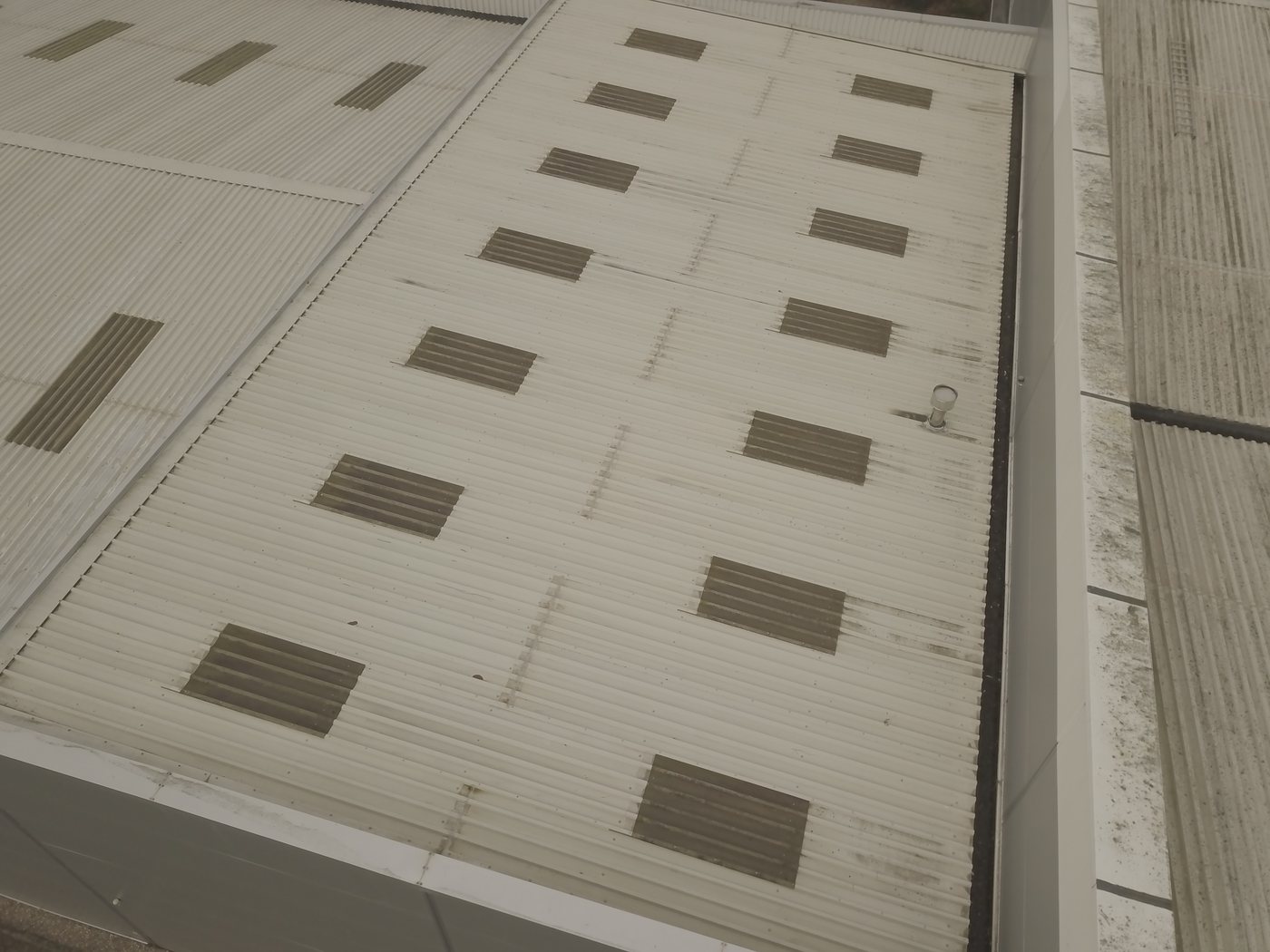
Purlin spacing affects solar structural calculations in two ways: it determines the maximum unsupported span of the roof sheet between fixing points, which governs sheet capacity under panel dead load and wind uplift; and it determines the available fixing positions for the racking system, which constrains the panel layout geometry. For buildings where purlin spacing is not documented in the drawings, it can be established by drone survey measurement from above or by on-site inspection. Desktop structural assessment assumes the documented spacing; deviations discovered on site require report amendment.
WHERE SOLAR SURVEYS ADDS VALUE
EUROCODE STRUCTURAL CALCULATIONS: SITE-SPECIFIC
Purlin capacity checks, dead load assessment, and wind uplift analysis using BRE Digest 489 are included as standard in every desktop structural report. Calculations are site-specific: wind speed derived from the site grid reference and altitude using EN 1991-1-4 and its UK National Annex, snow load checked against the UK ground snow load map for sites above 100m altitude. Where purlin capacity is marginal, the report states the maximum PV array dead load constraint rather than issuing a flat objection, preserving design flexibility for the installer.
CLIENT PROFILE
A solar installer encountered a 1985-era warehouse with Z-section purlins at 1,800mm spacing and a 7m span, a configuration close to the capacity limit for the proposed 14 kg/m² array dead load. The structural report issued a conditional clearance: the installation was viable subject to a maximum dead load of 12 kg/m² and minimum fixing density requirements at edge zones. The installer worked with the racking supplier to select a system within that envelope, and installation proceeded without structural objection.
THE STRUCTURAL TRINITY
Three Reports That Clear a Commercial Solar Site for Installation
READY TO COMMISSION
Get a Quote in 24 Hours.
Structural surveys, Desktop Structural Roof Loading Reports, drone assessments and solar design packages, delivered to a 48-hour benchmark.
Get a Quote