Portal frame construction accounts for the majority of commercial and industrial buildings in the UK, the single-storey sheds that house warehouses, distribution centres, manufacturing facilities, and agricultural buildings. It is also the most common building type for large-scale rooftop solar installation. Understanding how portal frames work structurally, and where the critical load-bearing elements are, is essential context for anyone managing a rooftop solar project on this building type.
How a Portal Frame Works Structurally
A portal frame is a rigid structural frame formed from steel columns and rafters connected by moment-resisting connections at the eaves and, on multi-bay frames, at the apex. The frame resists gravity loads and horizontal wind loads through the combined bending stiffness of the columns, rafters, and their connections, not through triangulated trusses or pinned joints.
The structural hierarchy in a typical portal frame building is:
- Primary frame: Steel portal frames spanning the full width of the building. Typically spaced at 5-7.5m centres. Columns and rafters are hot-rolled I-sections (Universal Columns and Universal Beams) to BS EN 1993-1-1.
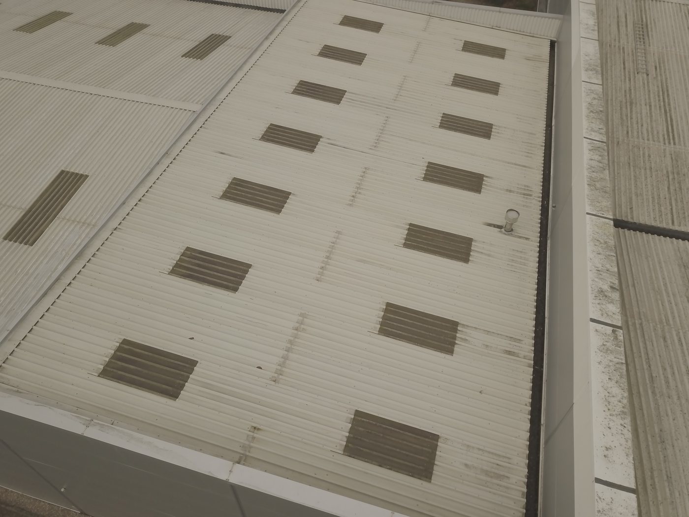
- Purlins: Cold-formed steel sections (Zed or Sigma profile) spanning between portal frame rafters. Typically spaced at 1.5-2.0m centres on the rafter slope. Purlins carry roof cladding, and are the first structural element encountered when loads are applied to the roof surface.
- Roof cladding / sheeting: Profiled metal sheeting (sinusoidal, trapezoidal, or standing seam) fixed to purlins. Carries self-weight and surface loads to purlins.
For solar PV structural assessment, the load path is: panel → mounting system → sheeting → purlin → rafter → column → foundation. Each element in this chain must be checked.
Portal Frame Purlins: The Critical Element for Solar PV
In solar PV structural assessments for portal frame buildings, purlins are almost always the critical structural element, not the primary frame. This is because purlins are designed as secondary elements carrying cladding loads only, and they have limited reserve capacity above their design load.
Virtually all purlins in UK portal frame buildings constructed since 1980 are cold-formed thin-gauge steel, typically 1.5mm, 2.5mm thick Zed or Sigma sections. Cold-formed sections behave differently from hot-rolled sections in structural design: they are susceptible to local buckling of the thin webs and flanges, and their capacity must be calculated to BS EN 1993-1-3 rather than BS EN 1993-1-1. The difference is significant: a cold-formed 200Z25 purlin (200mm depth, 2.5mm gauge) has a moment capacity of approximately 6.5 kNm, compared to an equivalent-depth hot-rolled section at over 30 kNm. Confusing the two calculation routes produces dangerously unconservative results.
Assessing Purlin Capacity for Solar PV
The structural assessment for a portal frame rooftop solar installation must establish the current loading on the purlins and calculate their residual capacity for additional solar array load. This requires:
Existing load quantification:
- Roof sheeting self-weight (from sheeting specification or measurement): typically 0.06-0.12 kN/m²
- Insulation and liner self-weight: typically 0.05-0.10 kN/m²
- Any imposed load from roof plant, maintenance access, or services: varies
Purlin section properties:
- Section depth, flange width, web height, and gauge, measured on site if drawings unavailable
- Material grade (typically S350 or S450 for cold-formed sections)
- Purlin spacing and span between primary frames
Residual capacity calculation: Using BS EN 1993-1-3, calculate the moment capacity of the purlin at its worst-case mid-span position, subtract the moment generated by existing loads, and verify that the remaining capacity exceeds the moment from the solar array dead load and wind uplift combination.
The wind uplift calculation is particularly important for portal frame buildings because the pitched roof geometry creates different pressure coefficients than flat roofs. BS EN 1991-1-4 NA specifies pressure zones for duopitch (typical portal frame) roofs that vary with roof pitch and wind direction. The engineer must check both the windward and leeward slopes under the wind direction that produces maximum uplift.
Rafter Assessment
For most standard portal frame buildings with lightly-loaded purlins, the primary frame rafter has adequate capacity to carry the solar array loads transferred through the purlins. However, rafter assessment becomes relevant when:
- The purlin assessment fails, and the question arises whether rafter reinforcement could allow a larger array
- The array layout is non-uniform and creates concentrated load on specific rafter bays
- The building has been modified, altered bay dimensions, removed or added bracing, that changes the load distribution
- The building is approaching the end of its design life and a general structural assessment is appropriate
Rafter assessment uses BS EN 1993-1-1 (hot-rolled sections) and requires knowledge of the rafter section, span, and connection details at eaves and apex. This information is typically available from original structural drawings; where drawings are absent, rafter dimensions can be measured on site during an intrusive survey.
Construction Year and Documentation Considerations
Portal frame buildings constructed before 1992, when BS 5950 Part 1 was the prevailing design standard, before the Eurocodes were introduced, may have been designed to slightly different loading assumptions. The differences between BS 5950 and Eurocode wind loading are modest for most locations, but the structural assessment must be conducted to current Eurocode standards regardless of the original design basis.
Buildings constructed before 1985 present higher documentation risk: original drawings are more likely to be missing, the steel sections used may be British Standard rather than European Standard sizes, and connection details may be non-standard. For these buildings, a site survey to measure actual section dimensions is typically required before the structural assessment can proceed.
Post-1992 portal frame (Eurocode era)
- Standard Zed/Sigma purlins, manufacturer load tables available
- Original drawings usually available from owner or building control
- Desktop report typically sufficient if drawings complete
- Standard fixing solutions likely adequate
Pre-1985 portal frame
- BS purlin sections, may not match current manufacturer tables
- Drawings often missing or incomplete
- Site survey typically required
- More likely to require structural reinforcement for larger arrays
Common Assessment Outcomes for Portal Frame Solar
Based on structural assessment experience across the UK commercial portal frame stock:
Standard post-1990 warehouse, full drawings, standard array: Structural adequate without modification in the majority of cases. Desktop report sufficient. Turnaround 48-72 hours.
1970s, 1980s portal frame, drawings absent: Site survey required. Purlins frequently found to be lighter gauge than modern equivalents. Array coverage may need to be reduced to 70-80% of roof area to keep within purlin capacity. Turnaround: 48 hours from the site visit.
Modified or extended buildings: Original and extension areas may have different structural characteristics. Assessment must address each area separately. Turnaround dependent on documentation availability.
Buildings with existing roof plant consuming capacity: Available capacity for solar reduced by existing loads. Structural assessment must quantify existing plant loads before calculating solar array residual capacity. Site survey required to confirm plant weights where records are absent.
Portal Frame Assessment in Multi-Site Programmes
For asset managers with portfolios of portal frame buildings, structural assessments can be streamlined significantly when buildings are of similar construction type and age. A master structural methodology for a specific building type, e.g., all 1995-2005 single-span portal frame warehouses in the portfolio, allows desktop assessments to be produced from a common calculation template, with site-specific inputs substituted for each building. This approach reduces per-site engineering time by 30-50% compared to unique assessments for each building.
Purlin Restraint and Lateral-Torsional Buckling
Cold-formed steel purlins in portal frame buildings are susceptible to lateral-torsional buckling (LTB), a failure mode where the compression flange of a beam under bending load buckles laterally before the full plastic moment capacity is reached. LTB is a critical consideration in purlin capacity calculations under BS EN 1993-1-3, and it is heavily influenced by the lateral restraint provided by the roof cladding.
In a standard portal frame building, the roof sheeting continuously restrains the top flange of the purlins against lateral movement, significantly enhancing their effective bending capacity above the unrestrained value. This "sheeting restraint" effect is quantified in the purlin manufacturer's load tables and in the BS EN 1993-1-3 calculation methodology.
For solar PV installations, the interaction between solar mounting systems and purlin restraint must be understood. A through-fix mounting system that attaches to the sheeting above the purlin is generally compatible with sheeting restraint, the sheeting continues to restrain the purlin top flange as intended. However, a mounting system that removes or compromises sections of the sheeting between purlins (e.g., to accommodate cable routes or tilt frame footings) may reduce the sheeting restraint along affected spans, and the purlin capacity must be recalculated accounting for the reduced restraint.
Portal Frame Modification Records
Commercial portal frame buildings are often modified over their operational lives, extensions, mezzanine additions, rooflight alterations, wall openings for loading bay doors, or removal of internal columns to create larger operational space. These modifications can change the structural behaviour of the frame in ways that affect solar PV structural assessment:
- Removal of internal columns in multi-bay frames: Extending a bay by removing a column changes the span of the primary frame and the purlins spanning between frames. Extended spans mean higher mid-span moments under the same load, a purlin adequate for its original 6m span may not be adequate for a 12m span created by a column removal.
- Rooflight replacement or addition: Adding rooflights requires cutting purlins or adding intermediate framing to form the rooflight opening. This can change the purlin continuity and load distribution in the affected area. The structural engineer must understand the current rooflight arrangement before calculating purlin capacity.
- Added plant supports: Roof-mounted plant (HVAC, ventilation, solar) added after the original construction creates concentrated loads on purlins that were not in the original design. A structural assessment for a new solar installation must account for existing plant loads before calculating available capacity for the new array.
The structural engineer must ask whether any modifications have been made to the building since original construction. This question cannot be answered from drawings alone, the building owner or estate manager must confirm modification history. Where significant modifications have been made without records, a site inspection to confirm current structural configuration is necessary.
Steel Specification and Grade in Portal Frame Buildings
The capacity of cold-formed steel purlins depends on the yield strength of the steel, the stress at which the steel begins to yield and plastically deform. UK portal frame buildings from the 1990s onwards typically use S350 or S450 grade cold-formed steel (minimum yield strengths of 350 and 450 N/mm² respectively). Buildings from the 1980s may use older British Standards grades that are equivalent to current grades, or may use thinner sections at lower grades.
Where the structural engineer cannot confirm the steel grade from specifications (because drawing specifications don't show grade, or specifications are not available), a conservative assumption of S350 is appropriate. Where the purlin is borderline under S350 assumptions, the engineer may specify a Vickers hardness test on an accessible purlin surface to confirm yield strength, higher hardness correlates with higher yield strength in cold-formed steel and can resolve a marginal calculation in either direction.
For buildings of unknown vintage or specification, grade uncertainty adds a margin of conservatism to the structural assessment that may result in a recommendation to reduce the array size or reinforce the structure, when in fact the structure is perfectly adequate at the correct (higher) material grade. Specifying a material test upfront on buildings where grade uncertainty is likely, rather than accepting conservatism by default, produces more accurate and ultimately more useful structural assessments.
Portal Frame Structural Assessment for EPC Contractors
EPC (Engineering, Procurement, and Construction) contractors who install commercial solar on a wide range of portal frame buildings benefit from developing a consistent structural assessment protocol that applies across their project portfolio. Rather than treating each project as a unique structural assessment challenge, an EPC that installs primarily on UK portal frame warehouses can develop a standardised assessment approach:
- Standard information pack for each site: drawings checklist, site information form, array layout template
- Pre-assessed mounting system types: standard seam clamp and through-fix systems pre-assessed for typical portal frame geometries and wind zones, so site-specific assessments are variations on a proven base case rather than first-principles exercises
- Framework structural engineer: one structural engineering firm briefed on the EPC's standard building types and mounting systems, able to process site-specific assessments efficiently within a consistent framework
This approach reduces structural assessment lead time and cost per site while maintaining technical rigour, each site still receives a site-specific assessment, but the structural engineer is not starting from scratch on each one.
Purlin and Sheeting Rail Capacity for PV Mounting Systems
In portal frame buildings, solar PV panels are typically mounted to the cold-formed steel purlins that span between the primary portal frame rafters. The purlins carry the panel dead load and wind loading from the PV installation in addition to their primary structural role of supporting the roof sheeting and transferring wind and snow loads to the primary frames. Purlin capacity for combined loading must be assessed using the cold-formed steel section properties, typically from manufacturer load tables for the specific purlin type (Zeta, Sigma, or equivalent proprietary section), and the relevant load combinations from the Eurocodes. The governing load case for purlin design under solar PV typically involves the combination of permanent load (sheeting dead load plus PV dead load) and wind uplift, since uplift reduces the net compression from the permanent load and may reverse the bending direction in sections designed with anti-sag bar restraint systems. Anti-sag bars and cleats that restrain purlins against lateral-torsional buckling under downward loading do not automatically provide equivalent restraint under uplift-reversal loading, and the structural engineer should confirm that the restraint system is adequate for the uplift load combination before issuing clearance.
Foundation Assessment for Portal Frames Carrying Additional PV Dead Load
Portal frame buildings resist lateral loads through frame action rather than shear walls, and the foundation design is integral to this lateral load resistance. Standard portal frame foundations are designed with a base fixity condition that affects the distribution of bending moments throughout the frame. Adding significant dead load to the portal frame rafters via solar PV panels increases the vertical reaction at the column bases and changes the moment demand on the foundations under combined vertical and lateral loading. For buildings where foundation information is available, a desktop review of foundation capacity under the proposed PV loading is part of a complete structural assessment. For buildings where foundation records are not available, which is common for industrial buildings where original design documentation is not held, the structural engineer may need to assess foundation adequacy on the basis of the visible column base arrangement and standard foundation assumptions, or recommend a ground investigation to establish soil bearing capacity and confirm foundation dimensions before proceeding with structural clearance.
WHERE SOLAR SURVEYS ADDS VALUE
Solar Surveys provides structural survey and desktop appraisal services for commercial solar installations across the UK. Our reports are produced by structural engineers and are accepted by lenders, insurers, planning authorities, and DNOs. We support EPCs, asset managers, commercial property owners, and PPA providers at feasibility, pre-construction, and post-installation stages. To discuss a structural survey or desktop report requirement, contact our team directly for a same-day response.
THE STRUCTURAL TRINITY
Three Reports That Clear a Commercial Solar Site for Installation
READY TO COMMISSION
Get a Quote in 24 Hours.
Structural surveys, Desktop Structural Roof Loading Reports, drone assessments and solar design packages, delivered to a 48-hour benchmark.
Get a Quote