Most structural engineering firms in the UK take two to four weeks to produce a structural feasibility report for a commercial solar PV installation. Some quote longer. At Solar Surveys, the benchmark is 48 hours from receipt of complete information to signed, Eurocode-verified report delivery.
That difference is not a compromise on engineering quality. It is the result of a defined technical methodology, purpose-built report software, and the volume experience that comes from processing over 2,000 desktop assessments per month. This article explains exactly what a desktop structural roof loading report involves, how the 48-hour benchmark is achieved, and when a desktop report is the right product for your project.
What a Desktop Structural Roof Loading Report Is
A desktop structural roof loading report is a Eurocode-verified engineering assessment of a building's structural capacity to support a proposed rooftop solar PV installation, produced without a site visit. It is a defined engineering deliverable, not a checklist, not a generic suitability note, and not a roof condition survey.
The report answers the following engineering questions:
- Can the existing roof secondary structure (purlins, rafters, joists) carry the additional dead load of the proposed PV array and racking system?
- Can the existing or proposed fixings resist the wind uplift forces generated by the array under design wind conditions for this site?
- Are the primary roof members (portal frame rafters, trusses, main beams) adequate under the combined loading?
- Is snow loading a co-dominant load case for this location, and if so, does the structure remain adequate?
- What installation constraints apply, maximum array dead load, fixing density requirements, exclusion zones?
The report is signed and dated by a qualified structural engineer (suitably qualified structural engineering professional). Under MCS MIS 3002 Section 5.9, this engineer signature is a compliance requirement, not optional documentation. It is what distinguishes a compliant pre-installation structural assessment from a self-certified installer checklist.
The Data Sources That Make Remote Assessment Reliable
The premise of a desktop report is that the structural information required to make a credible assessment exists before any engineer sets foot on site. For the majority of standard commercial and industrial buildings in the UK, this is correct.
Existing structural drawings. For buildings constructed or significantly altered after approximately 1990, structural drawings are typically available from the building owner, the original design engineer, or via building control submission records. These provide primary and secondary member sizes and spacing, connection details, original design load assumptions, and foundation information. With drawings, an engineer can perform a full dead load and wind uplift calculation with high confidence.
Construction typology benchmarks. UK commercial and industrial buildings from the post-war period follow well-understood structural typologies. A steel portal frame warehouse constructed between 1975 and 2005 uses predictable member sizes, connection types, and purlin spacing conventions. An experienced structural engineer who has assessed hundreds of buildings of this type carries the reference data needed to make well-reasoned engineering assumptions where drawings are not available.
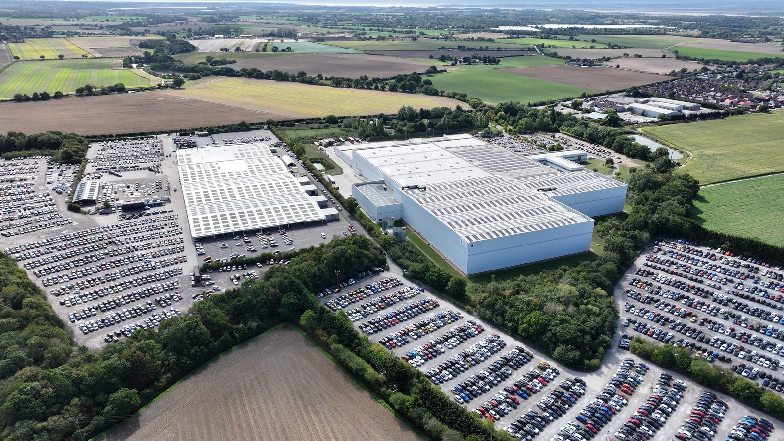
Remote imagery and public data. Satellite and aerial photography provides roof geometry, bay width, approximate span, roof type, and pitch. Ordnance Survey data, planning application records, and building control submissions provide construction date and use class. Combined, these sources allow the engineer to build a sufficient picture of the structural typology for most standard commercial buildings.
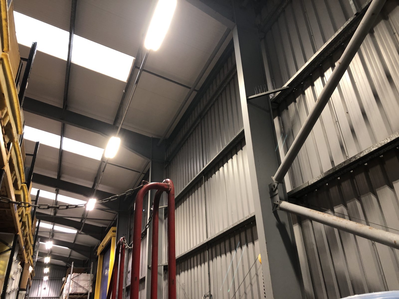
Client-supplied information. Where a client can supply photographs of the roof structure, recent condition inspection records, or basic dimensional information, the quality of the desktop assessment improves materially. The more information available, the more definitive the verdict. Solar Surveys provides a simple data request checklist at instruction to maximise the available information before the assessment begins.
The Calculation Methodology
Desktop structural feasibility reports at Solar Surveys are produced using Eurocode-based structural calculation. The applicable standards are EN 1991-1-3 (snow loads), EN 1991-1-4 (wind actions), EN 1993-1-1 (steel members), EN 1993-1-3 (cold-formed steel sections and sheeting), and the respective UK National Annexes.
Dead load capacity check. The proposed PV array dead load, typically 0.12 kN/m² to 0.20 kN/m² for a standard aluminium-framed crystalline silicon array on aluminium portrait racking, is added to the existing roof dead load. The combined dead load is applied to the secondary members (purlins or rafters) and the bending stress is calculated:
σ = M / Z | M = (w × L²) / 8
Where σ is the calculated bending stress, M is the applied moment, Z is the elastic section modulus of the purlin, w is the combined dead load per unit length, and L is the purlin span. The calculated stress is compared to the design strength py (typically 275 N/mm² for Grade S275 steel), applying the partial safety factor γf = 1.35 for dead loads per EN 1990.
Serviceability deflection is also checked: δ = (5 × w × L&sup4;) / (384 × E × I), compared to the limit of span/200.
Wind uplift analysis. Wind uplift is typically the critical load case for rooftop PV arrays. The site design wind speed is derived following the UK National Annex to EN 1991-1-4, extracting the fundamental basic wind velocity vb,0 from the national wind speed map, applying the roughness factor, orography factor, direction factor, and season factor to arrive at the peak velocity pressure qp(z). Array-specific pressure coefficients are taken from BRE Digest 489, which provides net uplift pressure coefficients for rooftop PV arrays at different tilt angles, positions within the array, and roof types. The design uplift force per fixing is compared to the characteristic pull-out resistance of the specified fixing system.
Snow loading. For sites in Scotland, Northern England, Wales, and elevated locations across the UK, snow loading is assessed per EN 1991-1-3. The characteristic ground snow load sk is taken from the national snow load map and corrected for altitude and roof slope. Snow drift accumulation behind and beneath the array is accounted for using the drift shape coefficient µi.
Why 48 Hours Is an Achievable Benchmark
The 48-hour delivery benchmark is a function of three factors: standardised calculation templates, proprietary report generation software, and the efficiency that comes from high-volume experience.
Standardised templates. For the most common commercial building types, steel portal frame warehouses, flat-roofed logistics units, light industrial units, a structured calculation template allows a qualified engineer to populate site-specific parameters and produce a signed report without recreating the calculation framework for each instruction. Standardisation removes non-value-adding administration from the engineering workflow without reducing the rigour of the structural assessment.
SOLAR_SURVEYS_v6 software. Our internal report generation platform handles data entry, calculation execution, output formatting, and report assembly. The engineer's time is focused on engineering judgement, reviewing the site data, setting the calculation parameters, validating the outputs, and identifying any non-standard conditions that require specialist treatment. Document production is automated.
Volume experience. At 2,000+ desktop assessments per month, the friction associated with every stage of the process has been identified and removed. A report that might take three days at a firm producing five reports per month takes significantly less time at a firm producing four hundred per week, not because the engineering is less thorough, but because the workflow is optimised and the engineer's reference knowledge base is comprehensive.
The industry standard turnaround for a desktop structural roof loading report is two to four weeks. Our benchmark is 48 hours. For project teams working to tight programme windows, that difference is material.
When a Desktop Report Is Not Sufficient
A desktop report produces one of three verdicts: structural clearance (installation can proceed as proposed), conditional clearance (installation can proceed subject to specific stated constraints), or referral to on-site survey.
Referral is the correct verdict when the desktop data is insufficient to confirm structural adequacy with confidence. This typically occurs when:
- No structural drawings are available and the building is of non-standard construction or pre-1960 vintage
- The proposed array dead load is at or above the estimated residual design capacity margin
- Photographic records or satellite imagery indicate signs of structural distress, significant corrosion, or roof deterioration
- The building is a complex or hybrid structure type where typology benchmarks are not reliable
- The installation contractor requires certified member dimensions for racking design that cannot be confirmed remotely
Referral to on-site survey is not an adverse outcome, it is an accurate and conservative assessment. It means the structural engineer has identified that a desktop assessment cannot reach a defensible conclusion, and that the additional data from a site visit is required. The desktop report in this case sets the agenda for the site survey, identifying the specific questions that need answering before sign-off can be issued.
Commissioning a Desktop Feasibility Report
To commission a Desktop Structural Roof Loading Report from Solar Surveys, we need the site address, the proposed array size (kWp or approximate panel count and roof area), and any structural drawings or site photographs you can provide. If no drawings are available, we proceed on the basis of available remote data, the vast majority of standard commercial buildings can be assessed to a conclusive verdict without drawings.
We confirm receipt of every instruction promptly and assign a qualified structural engineer to each assessment. Our standard delivery benchmark is 48 hours from the site visit.
The Role of Historical Aerial Imagery in Desktop Assessment
Historical aerial imagery, accessed through commercial satellite and aerial photography databases covering UK locations at resolutions of 10cm to 50cm/pixel, is one of the most useful tools in desktop structural assessment for buildings without original structural drawings. The imagery allows the engineer to observe the roof construction, identify structural bays, confirm roof covering type, assess visible condition, and in some cases measure structural dimensions directly from the image using calibrated tools.
Roof bay dimensions, the spacing between portal frame legs, visible from the pattern of roof lights, ventilation ridge units, or cladding sheet lap lines, can be estimated from calibrated aerial imagery with an accuracy of ±5-10%, which is sufficient for desktop assessment of standard industrial buildings where structural capacity margins are typically wider than 10%. For close-tolerance assessments on marginal buildings, this image-derived dimensional estimate will be accompanied by appropriate conservative factors or a recommendation for physical verification.
Historical imagery is also valuable for identifying building modifications. A building that appears as a standard portal frame in one imagery layer may show a structural extension, rooftop plant addition, or roof replacement in a later layer, evidence that the current structural condition may differ from the original design documentation. Identifying a modification from historical imagery allows the desktop engineer to adjust the assessment scope accordingly, potentially requesting supplementary data about the modification or flagging that the modification zone should be excluded from the clearance verdict pending further investigation.
Visible deterioration in historical imagery, corrosion staining on metal cladding, displaced or missing roof sheets, areas of apparent deflection in roof surfaces, can be used as early indicators of structural concern that may warrant on-site investigation before clearance is issued. A deterioration observation from desktop assessment is not itself a structural conclusion, surface staining may be cosmetic, deflection may be within the original design tolerance, but it informs the engineer’s judgment about whether a conservative assumption is adequate or whether physical verification is required.
Quality Assurance: The Check-and-Sign Process
The professional standard for structural engineering reports requires that all calculation work and report conclusions are independently checked by a second engineer before the report is issued under the signing engineer’s professional seal. This check-and-sign process is a quality gate that distinguishes professional engineering output from a commercial document, and its presence or absence is material to the report’s acceptability to MCS Scheme Providers, lenders, and insurers.
The check process verifies that: the input data is consistent with the information provided in the instruction pack; the calculation methodology is appropriate for the building type and loading scenario; the code references and factors are correctly applied; and the clearance verdict is a logical conclusion from the calculation results. The checker is typically a second engineer at the same or equivalent professional grade as the signing engineer, who reviews the work independently without sight of the calculator’s working notes, a cold check, in professional parlance.
In commercial desktop structural assessment for solar PV, the check-and-sign process must be completed before the signed report is issued to the client. A draft report, issued without the signing engineer’s final seal or with a “draft for comment” watermark, has not completed the check-and-sign process and should not be relied upon for regulatory submissions, MCS certification, or lender review. This is a common source of confusion in projects where programme pressure prompts clients to use a draft report for a downstream purpose before the final signed version is available: the draft may contain identical conclusions to the final version, but it does not carry the professional accountability of a signed and sealed document.
The practical implication for project managers: the 48-hour delivery benchmark for desktop structural reports refers to the signed final report, not an unsigned draft. Where a project timeline requires structural clearance evidence at a specific programme milestone, the instruction must be placed with enough lead time for the full check-and-sign process to be completed before the milestone date. A structural engineering firm that consistently issues signed reports within 48 hours of receipt of complete information has an efficient internal check-and-sign workflow, this is an operational capability worth confirming when selecting a structural survey provider for a time-sensitive programme.
Communicating Findings to Non-Technical Stakeholders
Desktop structural reports are professional technical documents, but their conclusions are acted on by a wide range of stakeholders who may not have structural engineering backgrounds: project managers, asset managers, financial analysts, legal teams, and planning officers all interact with structural clearance documentation at various points in the project lifecycle. A well-designed report communicates its conclusions clearly at both the technical and executive levels, ensuring that non-technical stakeholders can act on the report’s conclusions without misinterpretation.
The executive summary is the element of the report most frequently read by non-technical stakeholders. It should state the clearance verdict, list any conditions, and confirm the basis of the assessment (building type, proposed PV specification, assessment standard) in plain language accessible to a non-engineer. Technical calculation details belong in the body of the report, not the executive summary. A clear executive summary allows the project manager to understand the outcome and identify any action required without reading the full technical content, and allows the lender or insurer reviewing the document to confirm the clearance status without requiring their own engineering expertise to parse the calculations.
Conditions stated in the executive summary should be precisely worded. “Structural clearance is conditional on PV array dead load not exceeding 0.22 kN/m²” is actionable. “Structural clearance subject to light array” is not, it is vague in a way that creates uncertainty about what action is required and potentially inadequate for MCS certification or lender review. Reports where the executive summary and the conclusions section use consistent, precise language across both technical and non-technical sections are significantly easier to manage through the project lifecycle than those requiring interpretation at every downstream review point.
Desktop structural feasibility reports and pre-construction structural reports differ in purpose and scope, not in engineering methodology. A feasibility report answers the viability question from available data, may note what additional information would be required for pre-construction sign-off, and is typically produced at lower cost to match the feasibility stage budget. A pre-construction report is the definitive structural sign-off, produced from a complete data pack, suitable for MCS, G99, and lender submission. Both are delivered within 48 hours of receipt of complete information. Commissioning a feasibility report does not eliminate the requirement for a pre-construction report; it informs the decision of whether to proceed to that stage.
WHERE SOLAR SURVEYS ADDS VALUE
DESKTOP STRUCTURAL REPORTS: 48-HOUR BENCHMARK
Desktop structural reports for commercial solar PV are our primary deliverable. Every report is signed by a qualified structural engineer, produced to Eurocode EN 1991-1-4 and EN 1993-1-3, and includes site-specific wind uplift calculations using BRE Digest 489 methodology. The 48-hour benchmark applies from instruction confirmation to signed report delivery, for individual buildings and portfolio programmes. Reports are formatted from the outset to satisfy MCS MIS 3002 Section 5.9, DNO G99 submission, and lender TA requirements without reissue.
CLIENT PROFILE
An EPC contractor with 14 commercial sites under active development needed structural assessments to progress G99 applications. Sites ranged from 1980s portal frame warehouses to 2000s distribution centres. Reports were delivered in batches as site data was received, the first six reports were available within 48 hours of receipt of complete information, and G99 applications for those sites were submitted within the same programme week.
THE STRUCTURAL TRINITY
Three Reports That Clear a Commercial Solar Site for Installation
READY TO COMMISSION
Get a Quote in 24 Hours.
Structural surveys, Desktop Structural Roof Loading Reports, drone assessments and solar design packages, delivered to a 48-hour benchmark.
Get a Quote