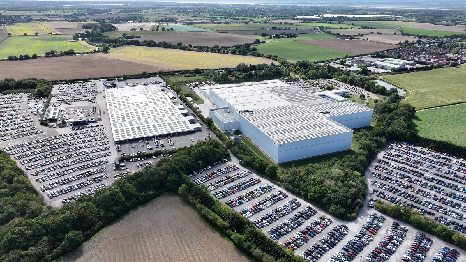
Drone photogrammetry for commercial rooftop solar uses the same UAV platforms and imagery capture techniques as standard drone roof surveys, but applies photogrammetric processing to the imagery to produce three-dimensional models of the roof geometry rather than two-dimensional orthomosaic plans. These three-dimensional models, commonly described as digital twins of the roof surface, provide geometric data that supports array layout design, shadow analysis, structural assessment, and as-built verification with a precision that two-dimensional imagery alone cannot deliver.
This article explains the photogrammetric technique, what it produces, how the outputs are used in the solar PV pre-installation process, and the specific applications where photogrammetric survey adds value over standard two-dimensional drone imagery.
How Drone Photogrammetry Works
Drone photogrammetry uses a technique called Structure from Motion (SfM), in which a large number of overlapping photographs (typically several hundred to several thousand, captured during a systematic grid flight pattern) are processed by photogrammetric software to reconstruct the three-dimensional geometry of the photographed surface. The processing identifies common feature points across multiple images taken from slightly different positions and camera angles, and triangulates the three-dimensional position of each feature point from the multiple image positions. The result is a dense point cloud, millions of three-dimensional coordinates, that represents the surface geometry of the roof at high spatial resolution.
The point cloud is then processed to produce a Digital Surface Model (DSM), a georeferenced three-dimensional grid of elevation values that represents the roof surface, and an orthomosaic: a geometrically corrected, two-dimensional aerial photograph of the roof produced by projecting the imagery onto the DSM and removing the geometric distortions caused by camera tilt and terrain relief. The DSM and orthomosaic together form the digital twin of the roof surface: a geometrically accurate, scaled, and orientated representation of the actual roof geometry.
Ground Control Points and Absolute Accuracy
The absolute accuracy of a photogrammetric survey, the degree to which the modelled geometry corresponds to the actual physical geometry of the roof in a real-world coordinate system, depends on the use of Ground Control Points (GCPs). GCPs are physical targets placed on the roof surface at known coordinates (measured by GPS or total station), which the photogrammetric processing uses to reference the model to an absolute coordinate system.
Without GCPs, photogrammetric models are internally consistent but are not referenced to an absolute coordinate system. They can be used for relative measurements (this surface is 150 mm higher than that one) but not for absolute positioning (this point is at OS grid reference X, Y, Z). For commercial solar pre-installation surveys where the outputs need to be integrated with site plans and building information models, GCPs are required to achieve the absolute accuracy needed for design coordination.
With appropriate GCP coverage, photogrammetric surveys of commercial rooftops can achieve absolute positional accuracies of 20 to 30 mm in plan and 30 to 50 mm in elevation using standard GNSS-enabled UAVs, and 5 to 10 mm in plan and 10 to 20 mm in elevation using RTK (Real-Time Kinematic) GPS-equipped UAVs. This level of accuracy is sufficient for array layout design, shadow analysis, and as-built verification of installed systems.
Applications in Solar PV Pre-Installation
The three-dimensional roof model produced by drone photogrammetry supports several specific applications in the solar PV pre-installation process:
Array layout optimisation. The DSM provides accurate roof slope, aspect, and profile data across the full roof surface. Where a large commercial roof has variable pitch, multiple roof sections at different elevations, or significant undulation, the three-dimensional model enables accurate inter-row shading analysis and optimised array layout in ways that two-dimensional imagery alone cannot support. The result is array designs that maximise energy yield within the constraints of the actual three-dimensional roof geometry.
Obstruction set-back calculation. Services, rooflights, and parapet details mapped in three dimensions enable accurate set-back distance calculation for each obstruction type. Where a roof has multiple HVAC units at different heights, the three-dimensional model allows accurate shadow calculation for each unit, enabling array layout to maximise coverage while maintaining the required clearances.
Drainage fall mapping. The DSM provides slope data across the roof surface that identifies drainage directions and fall gradients. Where flat-roof drainage design is inadequate, areas with insufficient fall toward drainage outlets, the photogrammetric model identifies these areas quantitatively rather than qualitatively. Drainage design for the post-installation roof can be planned using the DSM data.
As-built verification. A post-installation photogrammetric survey, compared with the pre-installation model, provides a geometric as-built record of the installed system: panel positions, mounting system heights, inter-row spacing, and any deviations from the design layout. This as-built record is valuable for O&M planning and for future re-roofing or system replacement projects.
Photogrammetric Survey as Part of Combined Pre-Installation Package
Drone photogrammetry is most efficiently combined with the standard drone roof condition survey as part of a single site visit. The imagery captured during the condition survey (with appropriate overlap and resolution) can be processed for both condition analysis and photogrammetric modelling without a separate flight. The additional processing time for photogrammetric model production is offset by the elimination of a separate survey visit.
For large or geometrically complex commercial rooftops where three-dimensional design coordination is specifically required, roofs with multiple levels, significant ridge variations, or complex obstruction patterns, photogrammetric survey adds a quantitative geometric dimension to the condition and structural survey package that enables design precision not achievable from two-dimensional imagery alone.
Digital Twin Applications in Long-Term Solar Asset Management
A photogrammetric digital twin of a commercial rooftop solar installation, a precise three-dimensional model of the roof surface, PV array, and associated equipment derived from drone survey imagery, has applications that extend well beyond the initial pre-installation survey. Understanding these long-term applications justifies the additional cost of photogrammetric processing over simple condition survey photography, particularly for high-value or long-duration assets.
Change detection is one of the most valuable long-term digital twin applications. By comparing a current photogrammetric model to a baseline model produced at a previous survey, the asset management team can identify dimensional changes in the roof structure or array configuration that may indicate structural movement, panel displacement, or racking deterioration. A racking foot that has shifted 15mm from its baseline position over three survey cycles is an early warning of progressive structural concern that would not be apparent from visual imagery alone. Change detection at millimetre precision, applied consistently over the asset lifetime, provides a quantitative structural monitoring tool that visual inspection cannot replicate.
Panel soiling and shading analysis is a second digital twin application that directly affects revenue performance. The digital twin’s three-dimensional geometry allows precise calculation of inter-row shading at any time of day and any day of the year, enabling comparison between modelled yield and actual metered yield to identify whether underperformance is attributable to structural shading, soiling, or electrical losses. This analysis supports O&M decision-making by quantifying the revenue benefit of cleaning, which varies significantly by array geometry and panel soiling rate across different parts of a large multi-bay roof.
Accuracy Standards and Calibration for Photogrammetric Models
Drone photogrammetry produces accurate models only when the survey is conducted with appropriate ground control, camera calibration, and image overlap. Understanding the accuracy achievable under different survey conditions allows asset managers to specify the level of accuracy required for their intended application and to evaluate whether a proposed survey specification is fit for purpose.
Ground control points (GCPs) are physical markers on or adjacent to the surveyed surface with precisely known coordinates, established by GNSS survey. When GCPs are incorporated into the photogrammetric processing, the model is registered to the real-world coordinate system at the accuracy of the GNSS survey, typically 10-30mm absolute accuracy with a differential GNSS receiver, and 5-15mm with a Real-Time Kinematic (RTK) survey. Without GCPs, photogrammetric models from commercial drone GNSS have absolute positional accuracy in the range of 50-150mm, which is adequate for condition monitoring but not for precise dimensional comparison across surveys conducted at different times without consistent reference.
For change detection applications, the critical accuracy requirement is not absolute positional accuracy but relative precision, the ability to detect movement between two surveys conducted with the same reference framework. Where a consistent GCP network is established at the first survey and used at all subsequent surveys, relative change detection at 5-10mm precision is achievable with standard commercial drone platforms. This precision level is sufficient to detect structural movement relevant to rooftop PV racking performance, and it is the accuracy requirement that asset managers should specify for monitoring applications rather than a generic accuracy target.
Camera calibration is the third accuracy determinant. Lens distortion and internal camera parameters affect the geometry of reconstructed models and must be calibrated either through a formal calibration target procedure or through an in-situ self-calibration during processing. Commercial photogrammetry software performs self-calibration automatically during model reconstruction, but the calibration quality depends on having sufficient image diversity in the capture dataset, varying viewing angles, altitudes, and illumination directions. Survey operators who fly fixed-altitude grids without camera tilt diversity may produce models with systematic geometric distortion that affects measurement accuracy. Confirming that the survey protocol includes appropriate camera diversity is a quality assurance step worth addressing in the survey specification before flight.
Drone roof surveys for commercial solar pre-installation produce a visual record of the roof surface from above, enabling identification of defects, services conflicts, drainage issues, and fixing zone conditions that cannot be reliably assessed from ground level on large commercial roofs. The survey deliverable is a condition report with annotated imagery, not a topographic dataset. The engineering value is in the condition assessment, not the data format.
WHERE SOLAR SURVEYS ADDS VALUE
DRONE PHOTOGRAMMETRY, 3D ROOF MODELS FOR COMPLEX COMMERCIAL SITES
Solar Surveys drone photogrammetric surveys produce georeferenced Digital Surface Models and orthomosaic plans for complex commercial rooftops. RTK-GPS equipped UAVs provide plan accuracies of 10-20 mm for design coordination. Photogrammetric processing is available as an addition to the standard drone roof condition survey, produced from the same imagery dataset. Outputs are provided in formats compatible with BIM, CAD, and PV design software for array layout and shadow analysis.
CLIENT PROFILE
A solar developer designing a 500 kWp installation on a multi-level industrial complex with three interconnected roof sections at different heights and orientations required accurate three-dimensional roof geometry to finalise the array layout and confirm inter-section shading calculations. A standard two-dimensional orthomosaic from the condition survey was insufficient for the shading analysis. Solar Surveys produced a photogrammetric Digital Surface Model from the same imagery dataset as the condition survey, providing elevation data at 50 mm resolution across all three roof sections. The design team used the DSM to finalise the array layout, confirm inter-row spacing, and complete the shading analysis. The combined condition and photogrammetric survey was completed in a single site visit with all outputs delivered within 72 hours.
The Technical Process: From Flight to Digital Twin
A drone photogrammetry digital twin is generated through a specific technical workflow that transforms raw imagery into a usable engineering model. Understanding this workflow helps clients specify what they actually need and evaluate the deliverables they receive.
Flight planning: The UAV flight is planned to cover the target area with sufficient image overlap for the photogrammetry reconstruction to work. For survey-grade outputs, side-overlap (between adjacent flight lanes) is typically 60-80%, and front-overlap (between consecutive images in a lane) is 70-90%. Higher overlap produces more reliable reconstruction but requires more flight time and produces larger data volumes.
Ground control points: For metrically accurate outputs (where measurements from the model will be used in engineering calculations), ground control points (GCPs) are established on the roof surface using surveying equipment. GCPs are fixed points with known coordinates that allow the photogrammetry software to scale and georeference the model accurately. Without GCPs, photogrammetric outputs have positional accuracy of ±2-5m; with GCPs, accuracy improves to ±30-50mm, sufficient for structural engineering use.
Point cloud generation: Photogrammetry software (Agisoft Metashape, RealityCapture, Pix4D) processes the overlapping images using structure-from-motion algorithms to produce a dense point cloud, millions of individual points in three-dimensional space, each with known coordinates and colour values from the imagery.
Mesh and orthomosaic: The point cloud is meshed (converted to a continuous surface) and textured with the original image colours to produce a 3D textured model. A top-down orthomosaic, a geometrically corrected 2D plan view at high resolution, is generated from the mesh for measurement and defect mapping purposes.
Engineering use: The structural engineer or solar designer imports the point cloud, mesh, or orthomosaic into their CAD or analysis software. Cross-sections, slope measurements, purlin positions, and drainage patterns can be extracted directly from the model without site access.
Accuracy and Engineering Applicability
The accuracy of photogrammetric outputs is critical for structural engineering applications. A point cloud with ±50mm positional accuracy is useful for roof slope mapping and array layout planning but may not provide sufficient accuracy for confirming purlin spacing for structural calculations, where a 50mm error in purlin spacing could change the section capacity check outcome.
For engineering-grade structural surveys, photogrammetry is used to supplement, not replace, direct measurement. The digital twin provides:
- Macro-scale geometry: roof slope, building dimensions, ridge height, drainage pattern, all accessible at ±50mm accuracy
- Defect mapping: visible surface defects georeferenced on the roof plan, useful for prioritising site investigation
- Array layout confirmation: confirming that the proposed array layout is consistent with the actual roof geometry, not just the drawing geometry
For confirming structural element positions and dimensions (purlin spacing, section depth) at the accuracy required for structural calculations, the point cloud provides a reference framework, but direct measurement by the surveyor or structural engineer remains the authoritative source.
BIM Integration and Handover
For commercial solar projects delivered within a BIM (Building Information Modelling) environment, photogrammetric data can be integrated with the project BIM model to create a construction phase record. The as-built solar installation can be documented in the BIM model by registering the photogrammetric point cloud against the design model and confirming positional accuracy.
At project handover, the BIM model including photogrammetric data provides the asset manager with a georeferenced record of the installation that can be updated during the operational period, adding subsequent inspection data, maintenance records, and any structural modifications to the same model. This creates a living asset record rather than a collection of disconnected reports filed at different points in the project lifecycle.
Cost and Accessibility of Drone Photogrammetry
Drone photogrammetry has become significantly more accessible and affordable over the past five years. For a standard commercial rooftop survey (5,000 m²), drone photogrammetry plus point cloud processing and orthomosaic delivery typically costs £1,500, £3,500 depending on accuracy requirements and deliverable format. This cost must be weighed against the engineering value of the output, a georeferenced roof model that supports structural assessment, array layout design, and asset management is significantly more valuable than the cost suggests.
For large commercial buildings (above 10,000 m²) or multi-building sites, drone photogrammetry becomes particularly cost-effective because the time and cost savings from eliminating multiple site visits accumulate rapidly. A portfolio of 20 commercial buildings could be surveyed photogrammetrically for less than the cost of a single traditionally-surveyed building at the same scale.
THE STRUCTURAL TRINITY
Three Reports That Clear a Commercial Solar Site for Installation
READY TO COMMISSION
Get a Quote in 24 Hours.
Structural surveys, Desktop Structural Roof Loading Reports, drone assessments and solar design packages, delivered to a 48-hour benchmark.
Get a Quote