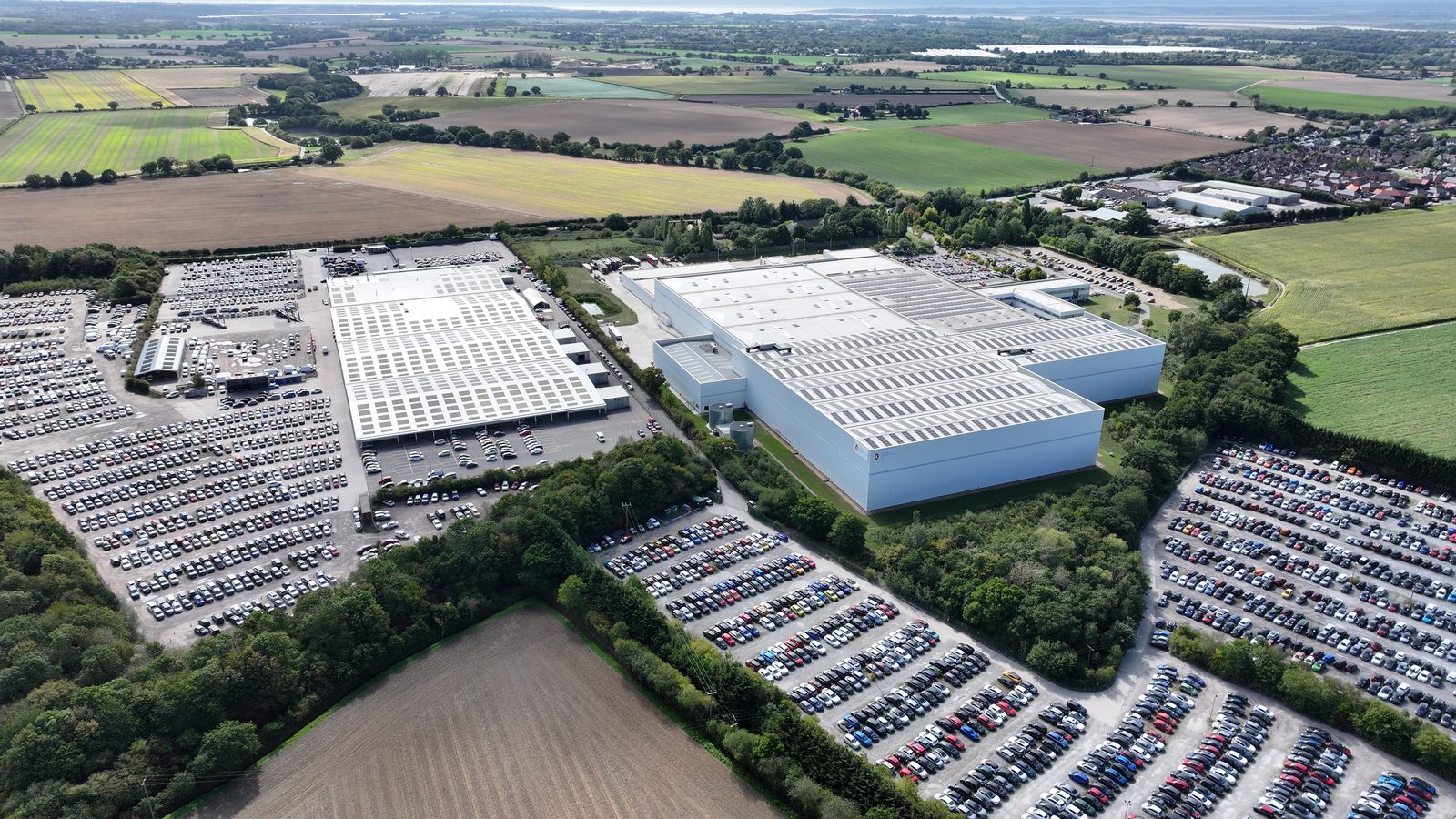
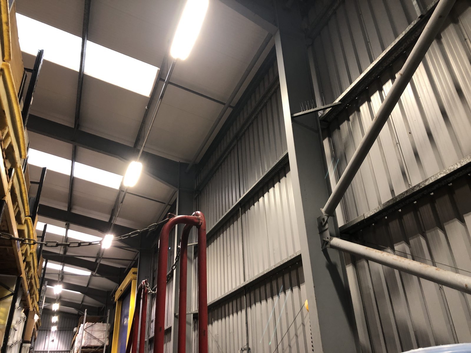
Pitched and flat commercial roofs are structurally and geometrically different in ways that directly affect how a desktop structural assessment is conducted. The primary load cases, dead load, wind uplift, and snow loading, behave differently on a pitched roof than on a flat one. The structural systems underlying them are different. The fixing options available are different. And the data required to assess them reliably by desktop methodology is different.
UK commercial rooftop solar installations divide roughly between two roof types: pitched roofs on steel portal frame warehouses and industrial buildings (typically 5 to 12 degrees pitch, steel cladding on cold-formed purlins), and flat or near-flat roofs on logistics units, retail stores, and commercial buildings (typically less than 5 degrees pitch, built-up felt or single-ply membrane on concrete decks or cold-formed flat roofing systems). A third category, pitched roofs on older industrial buildings with concrete or asbestos cement cladding, adds further variation.
This article explains the key differences in how desktop structural assessments are conducted for pitched and flat commercial roofs, covering dead load assessment, wind uplift methodology, snow loading considerations, and fixing system implications by roof type.
The Structural Differences Between Pitched and Flat Commercial Roofs
The primary structural system for a pitched commercial roof is typically a steel portal frame with cold-formed Z-section or C-section purlins spanning between main frames. The purlins support the roof cladding and are the structural members directly loaded by the PV array and its racking. The portal frame rafter and column carry the accumulated loads from the purlins. For a desktop assessment, the critical structural check is typically the purlin bending stress and deflection under combined existing dead load plus proposed array dead load.
The primary structural system for a flat commercial roof varies more widely by building type and age. Modern logistics buildings typically use a concrete frame or steel frame with a composite metal deck or concrete slab as the roof structure. Older flat-roofed commercial buildings may use a steel beam-and-block arrangement, a concrete flat slab, or a lightweight cold-formed flat roof truss system. The loading path for a PV array on a flat roof depends on how the array is mounted: ballasted systems (concrete blocks bearing on the roof membrane) load the deck directly, while mechanically fixed systems introduce point loads at fixing positions that must be traced to the underlying structure.
This structural diversity means that flat roof assessments are more variable in their methodology than pitched roof assessments. The pitched roof portal frame typology is relatively consistent; the flat roof structural type can vary substantially between buildings of similar age and use class.
Dead Load Assessment, How It Differs Between Roof Types
Dead load assessment for a pitched roof desktop report focuses on the secondary members, the purlins or rafters, because these are the elements loaded directly by the array and racking. The calculation involves adding the proposed array dead load (typically 0.12 to 0.20 kN/m² for a standard aluminium-framed crystalline silicon array on portrait racking) to the existing cladding dead load and checking the combined bending stress against the purlin design capacity.
For a flat roof desktop report, the dead load assessment depends on the mounting system. A ballasted flat roof system distributes the array dead load across a larger area of the roof membrane and deck, reducing the intensity of the point load at any individual fixing or bearing position. The desktop assessment checks the deck capacity under the distributed ballast load, which is typically a more straightforward calculation than the purlin stress check required for a pitched roof. A mechanically fixed flat roof system introduces discrete loads at fixing positions that must be assessed against the local structural capacity at those points.
The proposed system specification is more critical for flat roof assessments than for pitched roof assessments, because the mounting arrangement has a greater effect on the load distribution and therefore on the structural assessment conclusion. A flat roof desktop assessment specified against a ballasted system cannot be used to confirm adequacy for a mechanically fixed system, and vice versa.
Wind Uplift Methodology for Pitched Roofs
Wind uplift on a pitched roof PV array is assessed using BRE Digest 489, which provides net uplift pressure coefficients for roof-mounted PV arrays as a function of array tilt angle, position within the array (interior rows versus edge and corner rows), and roof pitch. The design wind pressure at the site is calculated from the EN 1991-1-4 methodology, using the site postcode to extract the fundamental basic wind velocity and applying terrain roughness, orography, altitude, and direction correction factors.
For a pitched roof installation, the array tilt relative to the roof is a critical parameter. A portrait-mounted array at 30 degrees on a 10-degree pitched roof sits at a combined angle of 40 degrees to horizontal, generating higher net uplift coefficients than the same array mounted at a shallower tilt on the same roof. The BRE Digest 489 coefficient selection is sensitive to this combined angle, and the calculation input must correctly represent the installed configuration rather than assuming a generic tilt angle.
The critical wind uplift load case for a pitched roof is typically at the array perimeter, where edge and corner uplift coefficients are significantly higher than interior values. The desktop assessment must check not only the interior of the array but the edge and corner positions, as these are where the highest fixing demands occur and where an inadequate specification is most likely to fail.
Wind Uplift Methodology for Flat Roofs, Edge Zones and Ballasted Systems
Flat roof wind uplift assessment applies the same EN 1991-1-4 and BRE Digest 489 framework but with different pressure coefficient zones and a different consideration for ballasted mounting systems. On a flat roof, the wind pressure zone distribution creates high uplift near the roof perimeter and parapet zones, reducing towards the interior of the roof. Array positioning on a flat roof therefore has a significant effect on the wind uplift demands.
For ballasted flat roof systems, wind uplift is resisted by the self-weight of the ballast blocks rather than by mechanical fixing to the structure. The desktop assessment confirms that the ballast weight specified is sufficient to resist the design uplift force at each zone of the array, with particular attention to the perimeter rows where uplift forces are highest. The BRE Digest 489 minimum ballast requirements provide a starting point, which must then be checked against the actual site wind speed and array geometry.
Ballasted flat roof systems present a structural paradox: the ballast that resists wind uplift also adds dead load. For flat roofs with limited residual structural capacity, the dead load of a fully ballasted system may exceed the available margin even when the system is structurally adequate from a wind uplift perspective. The desktop assessment must consider both load cases simultaneously and may recommend a lower-ballast system with supplementary edge mechanical fixings to balance the competing constraints.
Snow Loading, Why It Is More Critical for Pitched Roofs
Snow loading under EN 1991-1-3 is assessed for all UK rooftop solar installations, but its significance varies substantially by location and roof type. For flat roofs in lowland England, the characteristic ground snow load is relatively low (0.5 kN/m² or less at most locations), and snow loading is rarely the governing load case. For pitched roofs in Scotland, Northern England, Wales, and elevated locations throughout the UK, snow loading can be a co-dominant or governing load case alongside wind uplift.
For a pitched roof installation, snow accumulation patterns are more complex than for flat roofs. Snow sliding from a pitched roof can accumulate in the lower sections and valleys of an array, creating drift load cases that are significantly higher than the uniform snow load. The EN 1991-1-3 drift calculation for a PV array considers the array as an obstruction to snow movement and calculates the accumulated drift height and load distribution behind and beneath the array panels.
The combination of dead load, wind uplift, and snow loading must be considered as a combined load case for the critical design condition. The Eurocode load combination rules (EN 1990 Table NA.A1.2) require the engineer to consider the most onerous combination of variable actions, which may produce a critical load case that does not correspond to any individual load acting alone.
Fixing System Implications by Roof Type
The fixing system for a pitched roof installation is typically a hook bolt, rail clamp, or penetrating screw fixing anchored to or through the roof cladding into the purlin below. The desktop assessment confirms the pull-out resistance of this fixing type at the specified centres against the design uplift force per fixing. For standard steel cladding on Z-section purlins, fixing pull-out resistance data is available from manufacturer test data and can be verified against the calculated design uplift demand without a site visit.
For flat roof installations, the fixing option is typically a ballasted mounting system, a mechanically fixed system using root anchors penetrating the waterproofing layer, or a hybrid system combining reduced ballast with perimeter mechanical fixings. The choice of system has implications for both the structural assessment and the waterproofing warranty, and the desktop assessment should be conducted against the specific fixing system selected rather than a generic assumption.
Flat Roof Solar PV: The Distinct Structural Assessment Framework
Flat roof commercial solar installations present a substantially different structural assessment context from pitched roof equivalents, and applying the same analytical framework to both produces incorrect results. The differences begin with the structural system, flat roofs are more likely to be built with concrete deck or timber deck construction, whereas pitched roofs are almost universally metal profile sheeting over steel purlins, and extend to the wind load environment, the drainage implications, and the options available for array attachment.
Flat concrete roof decks present a structural capacity question that differs from purlin capacity calculations. The relevant check for a concrete flat roof with ballasted PV racking is the punching shear capacity of the concrete deck at each racking foot location, and the bending moment capacity of the deck span between structural supports if the deck spans between beams. Punching shear is particularly important for concrete slabs loaded by concentrated point loads: if the racking foot area is too small and the ballast too concentrated, the local stress in the concrete may exceed the punching shear capacity of the slab, creating a localised failure risk that distributed area load analysis would not identify. Ballasted racking systems on concrete flat roofs should specify a minimum base pad area for each racking foot, confirmed by the structural engineer as generating local contact pressures within the slab capacity.
Flat roof wind loads require specific attention to parapet and obstruction effects. Parapets around the roof perimeter create a recirculation zone in which wind loads on the PV array differ from the open-exposure model. For tall parapets relative to the panel height, the parapet provides significant wind shelter for arrays near the roof edge, potentially reducing uplift forces in zones that would be the most demanding under open-exposure assumptions. However, the shelter effect is accompanied by accelerated flow at the parapet top, which can create higher-than-predicted uplift on the leading edge of the parapet-proximate array. The structural assessment must use an appropriate wind load model for the specific parapet geometry, not a simplified open-exposure assumption.
When Roof Type Determines the Viable Installation Approach
The choice between pitched and flat roof installation approaches is not always a design preference, in some cases the building’s structural characteristics make one approach clearly more viable than the other, and the structural assessment outcome effectively determines which approach is followed.
Pitched metal roofs with cold-rolled steel purlins generally favour through-fixed portrait racking at the same pitch as the roof slope, as this approach generates the lowest additional wind loads on the structure (by maintaining the original roof aerodynamic profile) and provides a direct, well-characterised load path from panel to purlin to rafter to column. The additional dead load is distributed uniformly across the roof surface, and the wind loads are predictable using standard BRE Digest 489 methodology. For most standard UK industrial warehouses, this is the structural default and the assessment is correspondingly straightforward.
Where a pitched roof has marginal structural capacity for a south-facing portrait array, an east-west low-tilt alternative on the same pitched roof surface can reduce the effective wind load profile and the additional dead load per unit area. While east-west arrays on pitched roofs are less common than on flat roofs, the structural argument for them is identical: lower net wind loads and lower array self-weight translate to a more favourable structural clearance outcome on marginal buildings.
Flat roofs with limited structural capacity for either ballasted or through-fixed systems may point toward a lightweight east-west aluminium ballasted system as the only structurally viable approach. In these cases the structural assessment defines the installation approach rather than confirming a pre-chosen one. Developers and EPC contractors should be prepared to work with the structural engineer’s findings to identify the array type and layout that can be structurally cleared on the specific building, rather than insisting on a pre-defined system that the building cannot support.
Pitched Roof Structural Failure Modes: Recognising the Warning Signs
Structural failure of a pitched roof under PV loading does not happen suddenly or without warning in most cases. There is typically a progression of observable warning signs that, if identified and acted on before installation, prevent the installation from proceeding on a structurally inadequate building. Understanding these warning signs allows building owners, surveyors, and EPC contractors to identify situations requiring professional structural investigation before they become structural incidents.
Visible deflection in the roof profile, a sagging line between portal frame legs, a wave in the cladding surface, or a visible departure from the straight roof profile when viewed along the eaves, indicates that one or more structural members are either overloaded, corroded to the point of section loss, or have sustained impact or installation damage. Any visible deflection in a roof structure beyond approximately span/360 is sufficient cause to instruct a structural investigation before adding any additional load to the roof.
Corrosion at purlin-to-rafter connections is a second warning sign. The connection is the critical load transfer point between secondary and primary structure, and corrosion at the purlin bearing plate, cleat, or bolt group reduces the effective connection capacity. A connection that was adequate for the original roof dead load may not be adequate for the combined original plus PV additional load if corrosion has reduced its capacity. Visual inspection of connection corrosion is within the capability of any competent observer, but quantifying the residual capacity of a corroded connection requires a structural engineer and should be part of any on-site structural survey scope on buildings showing visible connection deterioration.
WHERE SOLAR SURVEYS ADDS VALUE
PITCHED AND FLAT ROOFS, FULL LOAD CASE COVERAGE
Solar Surveys assesses both pitched and flat roof commercial buildings to Eurocode EN 1991-1-4 (wind), EN 1991-1-3 (snow), and EN 1993-1-3 (cold-formed steel), applying BRE Digest 489 for PV-specific wind uplift coefficients. Dead load, wind uplift, and combined load cases are all addressed in every desktop report. Flat roof ballast calculations, pitched roof drift accumulation, and perimeter zone uplift assessments are standard outputs. Reports are delivered within 48 hours of receipt of complete information.
CLIENT PROFILE
A solar developer with a mixed portfolio of 22 sites comprising both pitched portal frame warehouses and flat-roofed logistics units required desktop structural reports across the full estate. The flat-roofed sites were specified for ballasted mounting systems and the pitched sites for hook-bolt fixing. Solar Surveys assessed all 22 sites within 48 hours of receipt of complete information. The ballasted flat roof assessments confirmed adequate deck capacity across 16 of the 18 flat-roofed sites; two required reduced ballast density with supplementary perimeter fixings due to low residual capacity. The pitched roof assessments confirmed adequacy across all four sites. All reports were formatted consistently for the portfolio due diligence documentation pack.
THE STRUCTURAL TRINITY
Three Reports That Clear a Commercial Solar Site for Installation
READY TO COMMISSION
Get a Quote in 24 Hours.
Structural surveys, Desktop Structural Roof Loading Reports, drone assessments and solar design packages, delivered to a 48-hour benchmark.
Get a Quote