A desktop structural roof loading report is only as good as the data the structural engineer has available. The engineering methodology, Eurocode dead load calculations, BRE Digest 489 wind uplift analysis, purlin stress checks, is consistent regardless of input quality. What varies is the degree of confidence with which conclusions can be drawn, and whether the assessment can reach a definitive verdict or must refer to on-site survey.
Understanding what data drives the engineering verdict, and what data merely improves it, allows project teams to prioritise their data-gathering effort. Not all information is equally load-bearing. Structural drawings have a fundamentally different effect on the assessment than a recent roof condition report. Knowing which data matters most, and what engineers do when optimal data is unavailable, helps project teams submit instructions that are immediately actionable.
This article divides the data inputs into three tiers based on their effect on the engineering assessment: data that changes the verdict, data that improves confidence without changing the verdict, and data the engineer can derive without client input. It then covers what happens when drawings are unavailable, how to obtain them, and how to manage data collection across a portfolio programme.
Tier 1 Data, Information That Changes the Engineering Verdict
Tier 1 data directly determines whether the assessment can reach a definitive structural clearance, a conditional clearance, or a referral to on-site survey. Without Tier 1 data, the assessment may still proceed, but on the basis of assumed parameters, and with a higher probability of concluding with conditions or referral.
Structural drawings are the most valuable single input. Drawings showing primary and secondary member sizes, spacing, and grade enable the engineer to perform calculations based on verified dimensions rather than typology assumptions. For buildings constructed after 1990, structural drawings are commonly available. For older buildings, they may require retrieval from the original engineer, building control records, or the current building owner's archives.
Proposed system specifications are equally important on the loading input side. The assessment requires the proposed panel dead load (typically stated in kg/m² or kN/m²), the racking system dead load, the proposed fixing type and centres, and the roof coverage area. Without these parameters, the engineer must assess against a provisional loading assumption, which may not match the system ultimately selected.
Array layout and roof geometry determine the wind pressure zones applied to the array. A large array on a flat roof with a 1.5-degree tilt behaves differently under wind loading than a high-pitch portrait array near a roof parapet. The array geometry feeds directly into the BRE Digest 489 calculation; incorrect or absent geometry data means the wind uplift calculation is based on assumptions that may not match the installed configuration.
Structural Drawings, How to Obtain Them and What They Must Show
Structural drawings are the single most impactful document a client can provide with a desktop structural report instruction. They enable the engineer to move from typology-based assumption to calculation-based verification, significantly increasing the confidence and definitiveness of the assessment.
For commercial buildings constructed after the mid-1980s, structural drawings are most likely held by one of the following parties:
| Source | Likelihood of holding drawings | How to request |
|---|---|---|
| Building owner or facilities manager | High for post-2000 buildings | Request O&M manual or H&S file, drawings often included |
| Original structural engineer | Moderate, depends on practice retention policies | Request via the engineer named on any available planning documents |
| Local authority building control | High for buildings with formal building control completion | Submit a Building Regulation Records Request (BRRR) |
| Planning portal application records | Moderate, structural drawings sometimes included in planning submissions | Search by address on the relevant local planning authority portal |
| Tenant or lease documentation | Low, structural drawings rarely included in lease packs | Request from the landlord directly |
For the drawings to be useful in a desktop structural assessment, they must show: the primary frame arrangement (column and rafter sizes and spacings); the secondary roof members (purlin or rafter sizes, spacing, and connection details); the roof sheeting type and self-weight; and the original design loads (including dead load, imposed load, wind load, and snow load where applicable). As-built drawings are preferable to design drawings if any structural changes were made during construction.
Tier 2 Data, Information That Improves Confidence Without Changing the Verdict
Tier 2 data does not typically change whether clearance is granted, but it improves the confidence with which the engineer can issue that clearance and reduces the likelihood of conditions being attached. Providing Tier 2 data typically results in a cleaner, more definitive report with fewer caveats.
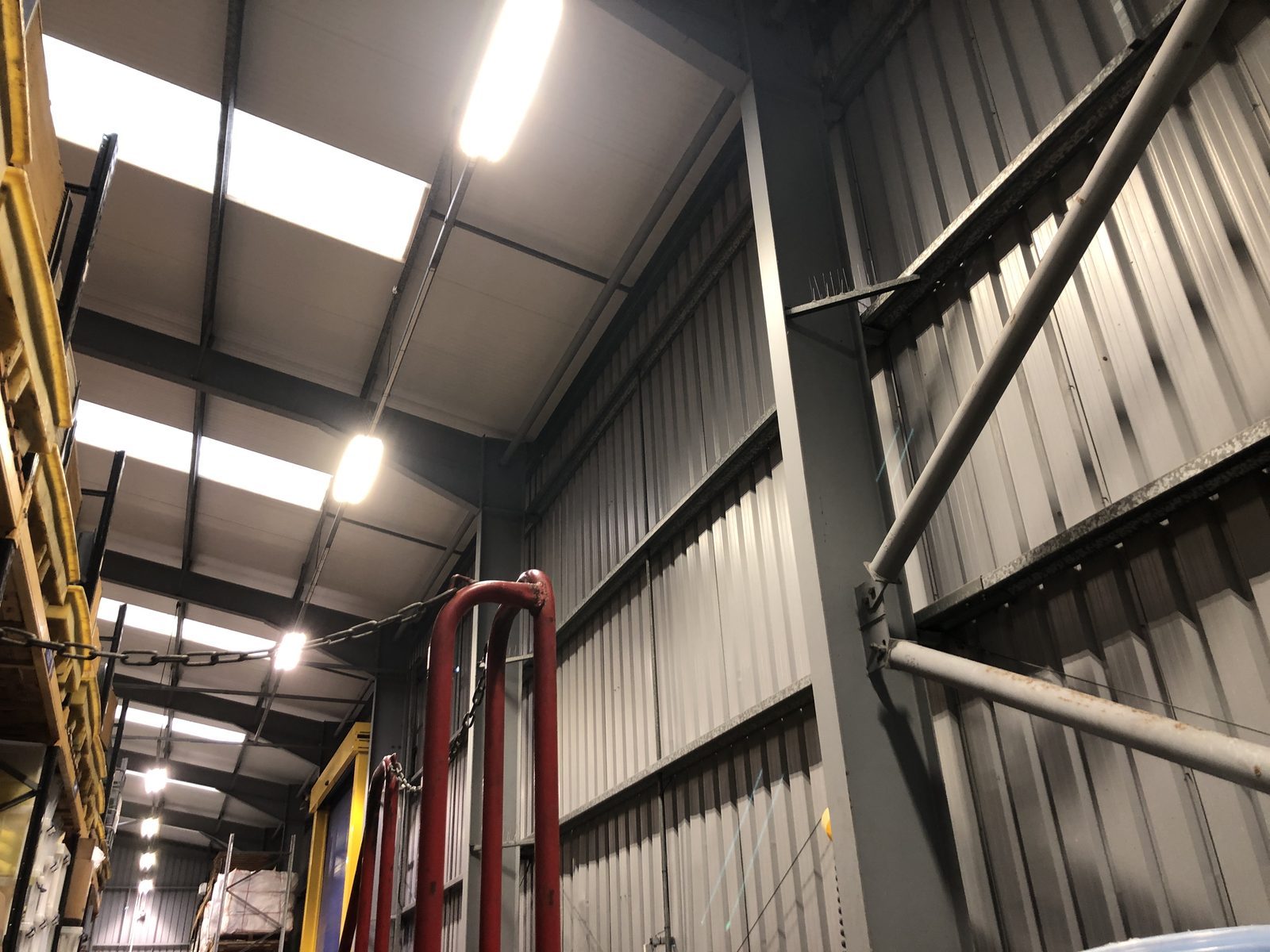
Internal roof structure photographs allow the engineer to visually confirm the structural typology, assess the condition of secondary members, and identify any signs of distress, corrosion, or modification that aerial imagery would not reveal. Photographs should show the purlin or rafter profile markings (typically stamped on the web), the member spacing at multiple bays, connection details at eaves and ridges, and any areas of visible deterioration or modification.
Recent maintenance or condition survey records inform the engineer of any known structural issues, recent modifications, or remedial works that might affect the assessment. A roof condition report noting that two bays of purlins were replaced three years ago, or that the cladding has been re-specified at a higher weight, is structural information that the desktop assessment should incorporate.
Confirmed construction date and planning history help the engineer select the most appropriate typology benchmark for buildings where no drawings are available. A building confirmed as constructed in 1988 will be treated differently to one estimated at 1975 based on aerial imagery alone.
Tier 3 Data, What the Engineer Derives Without Client Input
Tier 3 data is the information the structural engineer derives from available public sources and remote analysis, independent of any client input. Understanding what engineers can access independently helps project teams understand why desktop assessment is viable even when client-provided data is limited.
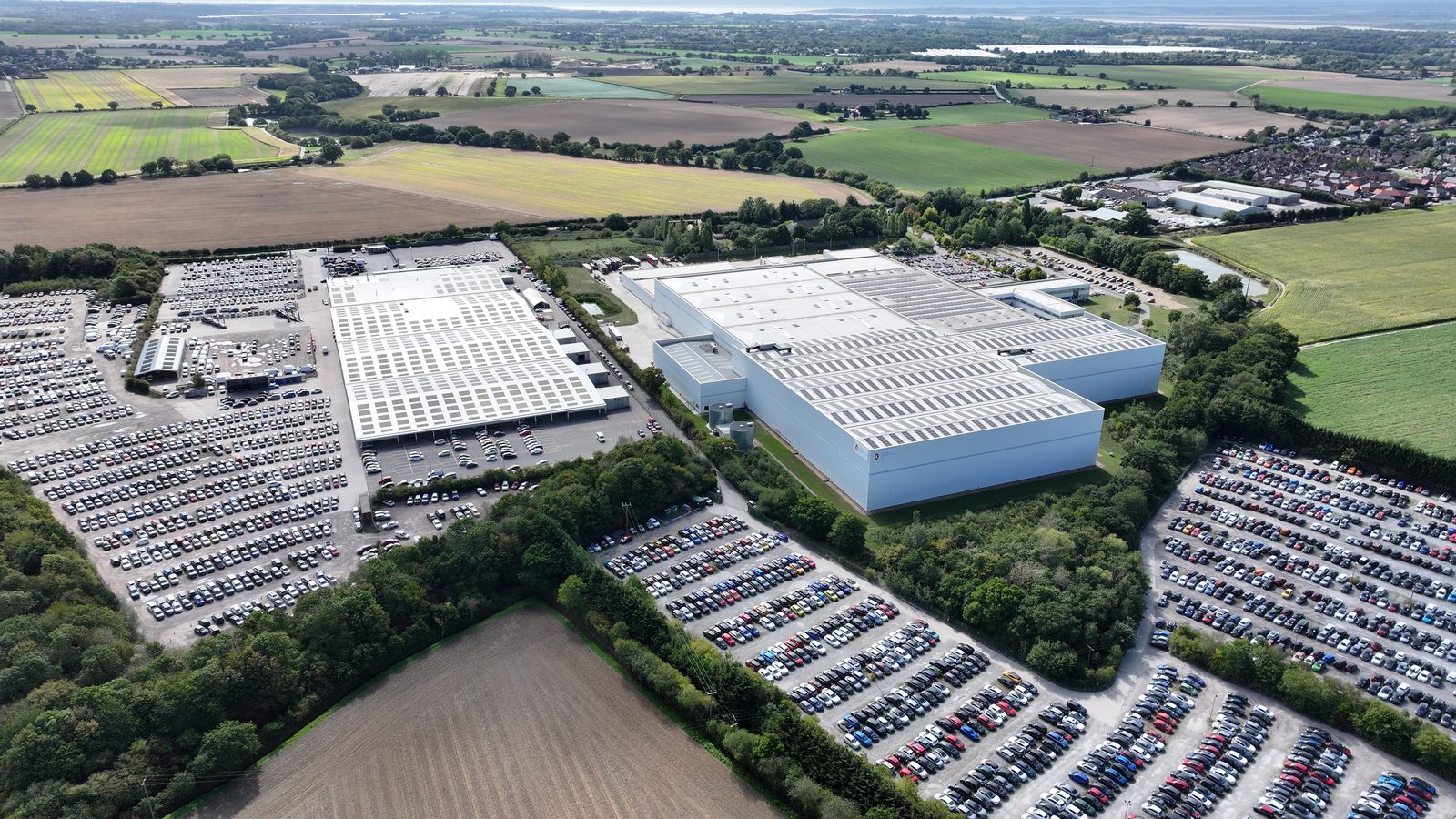
From satellite and aerial imagery, the engineer can determine roof geometry, bay width, approximate span, roof pitch and type, and the overall footprint of the structure. From Ordnance Survey mapping and planning records, the engineer can confirm the building's construction date range, use class, and any recorded extensions or alterations. From the postcode, the engineer can extract site-specific design wind speed using the UK National Annex to EN 1991-1-4, altitude correction factors, terrain roughness category, and characteristic ground snow load from the EN 1991-1-3 snow load map.
For standard UK commercial and industrial buildings of known typology, this combination of remote data and typology benchmarks allows the engineer to construct a credible structural model without client-supplied drawings. The assessment is less precise than a drawing-based calculation, but for standard portal frame warehouses and light industrial buildings, it is typically sufficient to reach a definitive verdict.
The No-Drawings Scenario, How Engineers Proceed
The absence of structural drawings is the most common data limitation encountered in desktop structural assessments. It is particularly common for buildings constructed before 1990, where drawing retention has been inconsistent. However, the absence of drawings does not automatically prevent a desktop assessment from reaching a definitive conclusion.
Where no drawings are available, the structural engineer uses typology benchmarks derived from volume experience with similar building types. UK steel portal frame warehouses from the 1975 to 2000 period, for example, follow predictable construction conventions: Z-section purlins at 1.4 to 1.8 metre centres, typical purlin depths of 150 to 200 mm, and Grade S275 steel throughout. An engineer who has assessed thousands of similar buildings carries the reference data to make well-grounded assumptions about member sizes and capacities.
The assumption approach introduces conservatism into the calculation. Where the engineer assumes the lightest purlin section consistent with the typology, they are checking adequacy against a conservative (worst-case) member. If the building actually has heavier purlins, as is common in buildings constructed for heavy industrial use, the actual capacity margin is wider than the assessment indicates. The conservative assumption protects the assessment from false-positive clearances.
Where the no-drawings scenario is combined with other uncertainty factors, non-standard construction, pre-1960 vintage, or loading at the capacity margin, the engineer may determine that typology benchmarks are insufficient for a definitive conclusion and refer to on-site survey. This is not a failure of the desktop process; it is the correct engineering response to genuine data insufficiency.
Portfolio Data Management, Standardising Input Across Multiple Sites
For EPC contractors, asset managers, and developers commissioning structural reports across multiple sites simultaneously, data management is as important as data quality. Inconsistent or poorly organised data packages submitted for a 50-site portfolio create friction at every stage of the assessment process, for both the client team assembling the instructions and the structural engineer receiving them.
The solution is a standardised data submission template: a spreadsheet with a consistent set of fields for each site covering address, construction date, building type, proposed array size, panel/racking specification, availability of drawings (with document reference), and any known structural issues. Sites without drawings are flagged separately so they can be assessed as a group against appropriate typology assumptions, rather than creating individual queries on each instruction.
A standardised template has an additional benefit: it makes the data review process faster for the structural engineer, which directly contributes to faster delivery. Engineers receiving consistently formatted data packages can process them more efficiently than engineers receiving ad hoc collections of emails, PDFs, and photographs of varying quality and completeness.
Setting Up an Instruction Process for Faster Turnaround
The instruction process itself affects delivery speed. An instruction that arrives with a complete data package, a stated delivery deadline, and clear output format requirements enables the structural engineer to begin work immediately. An instruction that requires follow-up data requests, format clarifications, or qualification questions before work can start adds hours or days to the timeline regardless of the engineer's capacity.
Establishing an agreed instruction protocol with your structural engineering provider, a standard data template, a confirmed delivery benchmark, a named contact for queries, removes the friction from each individual instruction. For high-volume programmes, this operational alignment can reduce the effective turnaround from instruction submission to report receipt by 30 to 50% compared to ad hoc commissioning.
The investment required is modest: one data template, one briefing session with the structural engineering firm, and one agreed format document. The return is structural assessments that arrive on programme rather than late, in a format that can be used without rework, and at a quality level that satisfies MCS, G99, and lender requirements without supplementary documentation.
Organising and Submitting Data Packages for Prompt Turnaround
A well-organised data submission significantly accelerates desktop structural report production. Rather than forwarding drawings, specifications, and survey data as a sequence of individual emails, compiling all available information into a single structured package at the point of instruction allows the structural engineer to commence assessment without iterative queries. A complete data package for a standard commercial roof desktop report should contain: as-built structural drawings or the most recent available survey drawings; a roof plan with the proposed array layout and panel positions clearly marked; manufacturer data sheets for the proposed panel model and racking system; and confirmation of the roof covering type, approximate age, and any known repair history. If the building has been subject to a condition survey, a copy of the survey report, even if focused on areas other than the roof, provides useful corroborating information about the structural condition of the wider building. Providing complete data at instruction eliminates the most common source of delay in desktop report production.
What to Do When Original Structural Drawings Are Not Available
A significant proportion of UK commercial buildings do not have retrievable original structural drawings, particularly pre-1980s industrial stock and older retail buildings. The absence of structural drawings does not automatically prevent desktop structural assessment, but it changes the methodology and may affect the confidence level achievable in the report output. Where original drawings are unavailable, desktop structural engineers rely on a combination of: visual interpretation of photographs and condition survey images to identify structural system type and approximate member dimensions; published span tables and structural data applicable to the identified roof construction; and load capacity back-calculations based on the age and type of construction. In some cases, a site visit by the structural engineer may be required to confirm structural system details before the desktop assessment can proceed. Communicating the absence of original drawings clearly at the point of instruction, rather than allowing the engineer to discover this mid-assessment, allows the engineer to advise upfront on whether a desktop approach remains viable or whether a site inspection will be required as a prerequisite.
When Data Gaps Emerge During Desktop Assessment
In some cases, data gaps that were not apparent at instruction become apparent only once the structural engineer is mid-assessment. A desktop review that begins with apparently adequate information may encounter ambiguities in structural drawings, sections that are unclear, member sizes that are not annotated, or loading information absent from the available documentation, that require supplementary input before the assessment can be completed. The structural engineer’s standard practice is to pause and issue a data request identifying the specific information required. The instructing party should treat this as an expected part of the process rather than an indicator of a problem, and respond as promptly as possible. Where the requested information is genuinely unavailable, the structural engineer may be able to proceed on the basis of stated assumptions, documented explicitly in the report, or may recommend an on-site inspection to resolve the outstanding questions before the desktop clearance can be issued.
WHERE SOLAR SURVEYS ADDS VALUE
48-HOUR DELIVERY, WITH OR WITHOUT DRAWINGS
Solar Surveys provides a data request checklist with every new client onboarding, so project teams know exactly what to gather before submitting an instruction. Where structural drawings are available, they are incorporated into a Eurocode-verified assessment from first principles. Where drawings are not available, our engineers apply volume-tested typology benchmarks to reach a definitive verdict for standard commercial buildings, no drawings required for the majority of UK portal frame and light industrial stock. Delivery benchmark: 48 hours from receipt of complete information.
CLIENT PROFILE
An asset manager with 42 rooftop sites across a mixed industrial portfolio needed desktop structural reports across the full estate before progressing to procurement. Structural drawings were available for 27 sites and unavailable for the remaining 15, all of which were standard portal frame warehouses constructed between 1978 and 1999. Solar Surveys provided drawing-based assessments for the 27 sites and typology benchmark assessments for the 15. All 42 reports were delivered within 48 hours of receipt of complete information per batch. Three sites were referred to on-site survey due to non-standard construction, identified at desktop stage rather than during installation.
THE STRUCTURAL TRINITY
Three Reports That Clear a Commercial Solar Site for Installation
READY TO COMMISSION
Get a Quote in 24 Hours.
Structural surveys, Desktop Structural Roof Loading Reports, drone assessments and solar design packages, delivered to a 48-hour benchmark.
Get a Quote