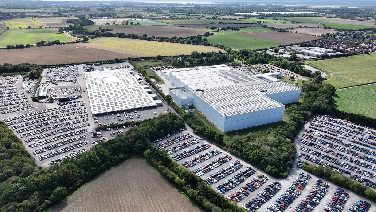
Battery Energy Storage Systems (BESS) co-located with commercial rooftop solar introduce a different and more demanding structural challenge than PV alone. Where a standard rooftop array imposes a relatively uniform distributed load across a large roof area, BESS cabinets impose concentrated point loads, typically 400-800 kg per unit, on specific structural locations. This distinction drives different structural assessment requirements, different risk profiles, and different engineering responses.
This article covers the structural engineering considerations for rooftop BESS co-location, the survey approach required to clear it, and the interaction between BESS and solar structural assessments.
Why BESS Structural Loads Are Different
A rooftop PV array distributes its load across the full array footprint, typically 10-18 kg/m² uniformly. A BESS installation concentrates load at discrete cabinet locations, each of which may impose 400-800 kg on a localised structural area of 0.5-1.5 m². The structural element directly below the cabinet, purlin, rafter, truss node, or slab, must carry this concentrated load without the load redistribution benefit that a distributed PV array enjoys.
The implication is that structural viability for BESS cannot be assessed at the whole-roof level alone. The engineer must assess:
- The capacity of the specific structural elements at each proposed cabinet location
- The adequacy of the roof deck or structure to transfer point loads to those elements
- The cumulative effect of BESS and PV loads on the structural elements beneath the combined footprint
- Any dynamic or vibration loads from thermal management systems within the BESS cabinets
BESS manufacturer data sheets typically quote cabinet weights in the range of 300-700 kg for utility-scale lithium-ion cabinet formats. However, installed weight can exceed quoted weight by 10-20% once cable trays, cooling units, fire suppression systems, and structural mounting frames are included. The structural assessment should use installed weight (confirmed with the BESS supplier) rather than catalogue weight. Undersizing the load calculation at this point produces a structural sign-off that may not hold once the fully-equipped cabinet is in place.
Rooftop vs. Roof-Adjacent BESS
For commercial rooftop solar installations, BESS is typically located in one of three configurations, each with different structural implications:
Rooftop BESS: Cabinets located on the roof alongside the PV array. Full structural assessment of the roof structure required at cabinet locations. Access requirements for maintenance must be factored into loading (personnel load + equipment loads during maintenance events). Fire safety considerations, thermal runaway, firefighter access, distance from building edge, are particularly complex on rooftops and require coordination with fire engineers.
Plant room / mezzanine BESS: Cabinets located within the building on a structural floor. Floor loading assessment required, the structural engineer assesses the floor slab or beam-and-block construction rather than the roof. Often more structurally straightforward than rooftop, but requires adequate ventilation, fire suppression, and safe cable routes between BESS and roof-mounted inverters.
Ground-adjacent BESS (external yard): Cabinets on ground-mounted frames adjacent to the building. Requires geotechnical assessment to BS EN 1997 rather than roof structural assessment. Simpler structural engineering but requires planning permission in most cases (change of use, development in curtilage) and additional civil works for hardstanding and cable routes.
The Structural Survey Approach for Rooftop BESS
A rooftop BESS co-location structural survey is more intensive than a PV-only desktop report. The key differences:
PV-only structural assessment
- Uniform distributed load calculation
- Section check on representative purlin/rafter
- Wind uplift on array perimeter zones
- Fixing pull-out assessment at spacing grid
- Desktop report typically sufficient if drawings exist
BESS co-location structural assessment
- Point load calculation at each cabinet location
- Local element check at each cabinet position
- Combined loading at areas where BESS and PV overlap
- Structural frame adequacy for concentrated loads
- Site survey frequently required to confirm section sizes at cabinet locations
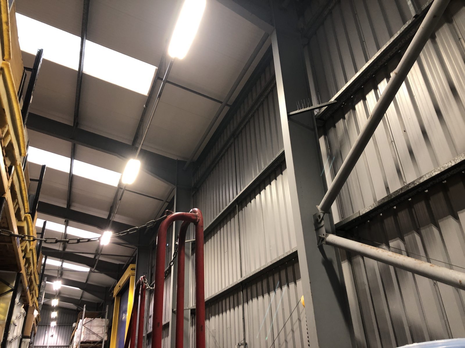
The site survey component is more often required for BESS assessments because the concentrated loads make the accuracy of structural element sizing more critical. A purlin that works under distributed PV load may fail under the concentrated load of a BESS cabinet placed midspan, and the difference between a 100×50 and a 150×65 cold-formed purlin section is the difference between adequate and inadequate.
Fire Safety Interaction with Structural Design
Rooftop BESS installations are subject to increasingly prescriptive fire safety requirements, particularly following the publication of updated guidance from the Fire Industry Association and the National Fire Chiefs Council. These requirements interact with structural design in several ways:
- Cabinet separation distances: Fire safety guidance specifies minimum separation between BESS cabinets, between cabinets and building openings, and between cabinets and the roof edge. These separation requirements may constrain cabinet placement, which in turn constrains where point loads are imposed.
- Suppression system loading: Automatic suppression systems (water mist, CO₂, inert gas) may themselves impose structural loads, tanks, pipework, and suppression heads add to the dead load at specific locations.
- Thermal runaway access routes: Firefighter access requirements may necessitate specific roof walkway structures, which themselves impose loads that must be assessed.
The structural engineer for a rooftop BESS installation should be coordinating with the fire engineer from the outset of design, not treating fire safety as a separate workstream that can be resolved after structural sign-off is obtained.
Grid Connection and DNO Requirements for BESS
BESS co-located with rooftop solar operates under a G99 grid connection (for systems above 16A per phase). The G99 application for a combined solar-plus-storage system is more complex than for solar alone, because the BESS discharge profile must be modelled alongside solar generation to demonstrate that the combined export does not exceed the consented export limit at any operating point.
Structural sign-off for the BESS component is required before G99 installation notification can be submitted, just as it is for the solar component. The DNO will not accept a connection notification for an installation that has not been structurally cleared.
What a BESS Co-Location Structural Report Should Contain
A complete structural report for a rooftop solar-plus-BESS installation should include:
- PV array assessment: distributed dead load, wind uplift by zone, fixing adequacy, structural element capacity
- BESS cabinet assessment: point load calculation for each cabinet, local element capacity at each location, combined loading at overlap areas
- Access and maintenance loading: personnel load during maintenance, any equipment load during commissioning or replacement events
- Suppression and fire safety structural elements: loading from suppression system, walkways, separation structures
- Overall structural adequacy statement, signed by structural engineer, with PI confirmation
- Any conditions attached to clearance: e.g., "cabinet locations as shown on drawing ref. X only", "no modification to structural elements without further assessment"
Programme Implications
BESS co-location structural surveys take longer than PV-only desktop reports. For a combined solar-plus-storage installation, allow four to eight weeks from instruction to structural sign-off, assuming a site visit is required. Projects that treat structural sign-off as an end-of-programme activity will create procurement delays at the point of installation.
The most efficient sequencing is to appoint the structural engineer at the same time as the BESS supplier is engaged, so that the structural assessment is conducted against confirmed cabinet specifications and layout rather than indicative data. Cabinet weight changes during the supply chain are not uncommon, early engagement allows the structural engineer to be briefed on finalised specifications before committing to a clearance opinion.
Battery Chemistry and Structural Considerations
Not all battery technologies have the same structural implications. The UK commercial BESS market is currently dominated by lithium-ion chemistries, primarily lithium iron phosphate (LFP) and nickel manganese cobalt (NMC). Each has different safety and structural characteristics that affect rooftop installation requirements.
Lithium iron phosphate (LFP): Lower energy density than NMC, meaning physically larger cabinets per MWh of capacity. More thermally stable, lower risk of thermal runaway at the same temperature. Fire safety requirements for LFP-based BESS on rooftops are less demanding than for NMC, which typically translates to less onerous structural requirements for fire suppression systems and separation distances.
Nickel manganese cobalt (NMC): Higher energy density, more capacity in a smaller, lighter cabinet. More thermally active, higher thermal runaway risk, requiring more stringent fire safety provisions. Fire suppression system requirements for NMC on rooftops are more demanding, and the structural loading from suppression systems (tanks, pipework, heads) is correspondingly greater.
The structural engineer must understand the battery chemistry being proposed before assessing the rooftop suitability, because it affects both the cabinet weight (and therefore point load at cabinet positions) and the suppression system weight (an additional distributed or concentrated load depending on system type).
Structural Survey Deliverables for BESS Projects
A BESS co-location structural report for a rooftop solar installation is more complex than a PV-only report and typically runs to a larger page count. The key additional elements in a BESS co-location report:
- Cabinet position plan: A drawing showing the structural assessment for each cabinet position, the element checked, the design load, and the capacity result. This drawing-based evidence is more useful for installation supervision than a narrative report describing each position in sequence.
- Combined loading check: Where PV arrays and BESS cabinets occupy overlapping or adjacent roof areas, the structural assessment must show the combined loading check, PV dead load plus BESS point load on the same structural element, under the governing load combination.
- Suppression system structural clearance: Confirmation that the structure can carry the suppression system loads at the proposed installation positions. This may be a brief additional section rather than a full separate assessment, depending on the suppression system weight.
- Maintenance access loading: BESS cabinets require periodic maintenance, inverter replacement, module swaps, thermal management servicing. The structural assessment should confirm that maintenance access loads (personnel load plus equipment handling load) at each cabinet position are within structural capacity.
Regulatory Context for Rooftop BESS
Rooftop BESS installations are subject to regulatory requirements beyond the structural sign-off, planning permission (for installations above certain sizes or on restricted sites), fire safety compliance (Building Regulations Part B and specific BESS guidance from the National Fire Chiefs Council), and G99 connection requirements for the combined solar-storage system. The structural assessment must be consistent with the fire safety design and the G99 connection specification, changing cabinet positions to resolve a structural issue may require fire safety distances to be recalculated.
The most efficient approach is to have structural engineering, fire engineering, and electrical engineering inputs running concurrently and co-ordinated throughout the design process, rather than resolving each discipline sequentially and then discovering conflicts at sign-off.
Structural Loading from BESS Equipment: Cabinet Weights and Floor Capacity
Battery energy storage systems installed on commercial rooftops impose concentrated structural loads that differ fundamentally from the distributed loads of a PV array. A BESS cabinet, depending on its chemistry and capacity, typically weighs between 400 kg and 2,000 kg per module. When multiple modules are grouped in a battery block with associated power conversion system (PCS) and switchgear, a complete BESS installation may concentrate 10,000-50,000 kg of equipment weight into a relatively small roof area, generating floor pressures far in excess of standard industrial roof loadings.
For rooftop BESS co-location with solar PV, the structural assessment must evaluate the concentrated point loads from BESS cabinets against the structural capacity of the roof zone where the BESS is proposed. This is fundamentally different from the distributed area load analysis applicable to PV racking. A standard industrial roof purlin may be adequate for a PV array dead load of 0.18 kN/m² across its full tributary area while being completely inadequate for a 1,500 kg BESS cabinet positioned at mid-span. The loading geometry matters: point loads at the worst structural location (mid-span of a simply supported purlin or rafter) generate bending moments that are far more severe than the same total weight distributed uniformly.
The structural response for rooftop BESS is therefore typically one of three approaches: positioning the BESS directly over or adjacent to primary structural supports (column heads, portal legs) where the load path is direct and the imposed moment on spanning members is minimised; distributing the BESS cabinet loads onto a structural spreader frame that transfers the concentrated loads to multiple purlin attachment points; or identifying that the roof structure cannot support rooftop BESS and recommending ground-level or car park canopy installation of the BESS equipment instead. Each approach has cost, programme, and operational implications, and the structural assessment should confirm which approaches are viable and what the associated structural requirements are.
Fire Safety and Structural Separation Requirements
Lithium-ion battery energy storage systems present a fire safety risk that is distinct from conventional rooftop electrical equipment. Thermal runaway in lithium-ion cells can generate temperatures exceeding 500°C and propagate rapidly through a battery module, producing toxic gases and potentially causing structural damage through heat exposure. Rooftop BESS installations must meet fire safety requirements that interact with the structural assessment in specific ways.
The relevant UK guidance for BESS fire safety on commercial premises includes BS 8519 (Selection and installation of fire detection and fire alarm systems), NFPA 855 (which is the dominant US standard increasingly referenced in UK engineering specifications), and the guidance published by the Association of British Insurers (ABI) on BESS fire risk management. Structural considerations in this guidance include: minimum separation distances between BESS equipment and other structural elements or building penetrations; the fire resistance rating of structural elements in proximity to BESS equipment; and the requirement for structural elements exposed to potential BESS fire events to maintain integrity for a specified fire resistance period.
For rooftop BESS installations, the structural assessment must confirm that the structural frame elements in proximity to the BESS are either inherently fire-resistant to the required period (typically 30 or 60 minutes depending on the insurer’s requirements and the building use) or that the BESS is positioned with sufficient separation from structural elements to limit the structural fire risk. In practice, many insurers require that rooftop BESS is positioned on a fire-resistant structural base, separated from the main building by fire-resistant barriers, and equipped with automatic suppression. The structural implications of these requirements, additional floor loading from the base construction, penetrations in the roof for suppression pipework, structural attachments for fire barriers, must all be assessed as part of the combined BESS and solar structural review.
DNO and Grid Connection Requirements for Co-Located BESS
Battery energy storage systems co-located with solar PV have specific grid connection requirements under Engineering Recommendation G99 that differ from solar-only connections. The BESS has the ability to import power from the grid as well as export, which places it in a different category from a generation-only asset and may require specific protection settings, metering arrangements, and connection agreements that the structural assessment must be aware of even if it does not directly address them.
The structural relevance of DNO requirements for co-located BESS arises in two areas. First, the DNO may require the BESS and its associated switchgear to be located at specific positions on the site to enable metering and disconnection access. This locational requirement may constrain where on the roof the BESS can be positioned, and may conflict with the structural engineer’s preferred location from a load path efficiency perspective. Resolving this conflict requires coordination between the structural engineer, the BESS equipment supplier, and the DNO connection team before the structural assessment is finalised.
Second, some DNO connection agreements for large BESS installations require the BESS to be capable of controlled shutdown in response to a network signal. This requirement affects the BESS inverter specification and protection relay settings, and may have implications for the structural support design if the required equipment configuration differs from the layout assumed in the structural assessment. Confirming the DNO’s specific equipment and location requirements before structural assessment is finalised avoids having to revise the structural scope after the assessment is issued.
WHERE SOLAR SURVEYS ADDS VALUE
BESS CO-LOCATION STRUCTURAL ASSESSMENT, POINT LOAD AND FIRE SAFETY ANALYSIS
Solar Surveys provides combined structural assessments for co-located solar PV and BESS rooftop installations, addressing the distinct loading regimes of distributed PV arrays and concentrated BESS cabinet point loads in a single coordinated report. Assessment covers BESS cabinet weight, spreader frame requirements, purlin and rafter capacity at point load locations, fire safety separation requirements, and structural implications of rooftop suppression and barrier systems. Reports are issued within agreed timescales and accepted by insurers and lender technical advisors on first submission.
CLIENT PROFILE
A commercial solar developer adding 500 kWh of rooftop BESS to an existing 800 kWp PV installation discovered during structural assessment that the proposed BESS cabinet position, mid-span of existing purlins, generated bending moments exceeding purlin capacity by 40%. The structural assessment identified three alternative positions adjacent to portal frame legs where the load path was direct, and recommended a steel spreader frame to distribute BESS cabinet loads across four purlin attachment points at each position. The revised layout was structurally viable without strengthening of the primary frame. The developer redesigned the BESS platform around the structurally feasible positions and achieved clearance at first submission.
THE STRUCTURAL TRINITY
Three Reports That Clear a Commercial Solar Site for Installation
READY TO COMMISSION
Get a Quote in 24 Hours.
Structural surveys, Desktop Structural Roof Loading Reports, drone assessments and solar design packages, delivered to a 48-hour benchmark.
Get a Quote