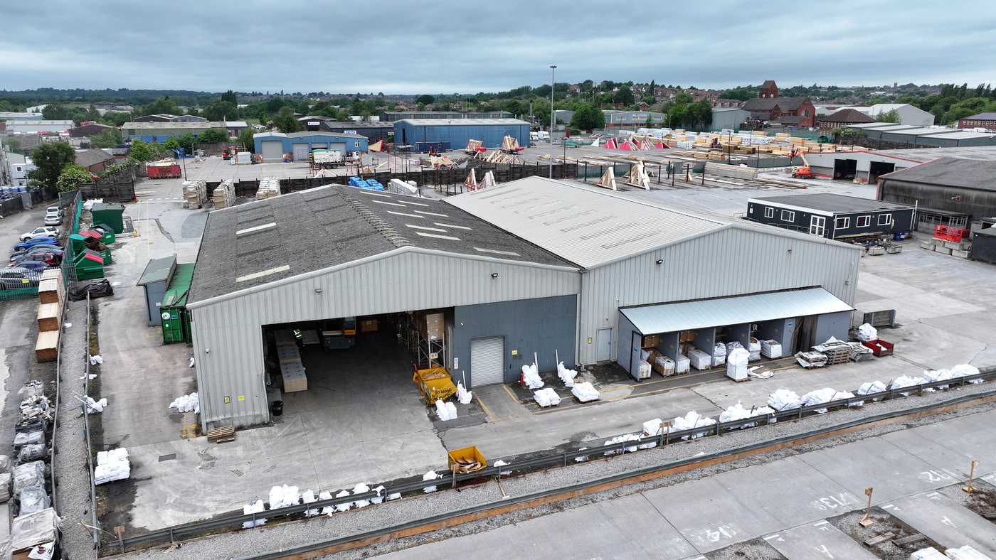
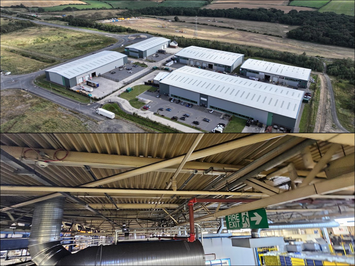
The industrial sector, encompassing manufacturing plants, processing facilities, distribution centres, and heavy industrial buildings, offers some of the UK's largest and most commercially attractive rooftops for solar PV. Industrial buildings are typically large single-storey structures with extensive, unobstructed roof areas, and their energy consumption profiles are well-suited to solar generation. However, the structural engineering requirements for solar on industrial roofs are more complex than for standard commercial buildings, and the survey approach must be designed to address factors that are unique to this building type.
This guide covers the structural engineering considerations for industrial solar installations, the building types most commonly encountered, and how to structure the assessment programme for industrial facilities.
Industrial Building Types and Their Structural Characteristics
The industrial sector encompasses a wide range of building types, each with distinct structural characteristics:
Light steel portal frame industrial buildings: The most common type for modern industrial estates. Single-span or multi-span portal frames with cold-formed purlins and profiled metal cladding. Generally well-documented (planning drawings available) and structurally straightforward for solar PV assessment. Most post-1990 buildings in this category can carry a standard solar array without structural modification.
Heavy industrial buildings with overhead cranes: Manufacturing facilities using overhead cranes (EOT cranes) have structural systems designed for dynamic crane loads. The structural frame is typically heavier hot-rolled steel with gantry girders. Roof loads from solar PV are unlikely to be critical for the primary frame, the frame was designed for much heavier crane loads. However, the roof secondary structure (purlins) may be independent of the crane design and should still be checked.
Reinforced concrete frame industrial buildings: Older industrial buildings from the 1940s, 1970s often use reinforced concrete frames, sometimes with pre-cast concrete roof panels or profiled metal roofing on concrete purlins. The structural assessment approach differs from steel frame buildings: concrete section capacity checks to BS EN 1992-1-1 rather than BS EN 1993-1-3 for cold-formed steel.
Specialist industrial structures: Some industrial buildings have specialist structural features, refractory-lined walls, acid-resistant floors, explosion-relief panels, or pressurised clean rooms, that affect roof structural access and survey methodology. The structural engineer must understand the operational context of the building before conducting an intrusive survey.
Buildings designed to carry overhead travelling cranes are designed for dynamic loads that are significantly larger than solar array dead loads. A 5-tonne EOT crane on a 20m span building imposes a wheel load of approximately 50-60 kN on the gantry girder. The solar array dead load on the same building might total 150-200 kN across the entire roof. The gantry girder design load exceeds the total solar array load by an order of magnitude. The constraint for solar on crane buildings is almost always the roof secondary structure (purlins), not the primary frame that supports the cranes.
Vibration and Dynamic Loads in Manufacturing Buildings
Manufacturing and processing facilities often contain plant and equipment that generates vibration, presses, compressors, crushers, fans, and rotating machinery. These vibrations are transmitted through the building structure and can affect solar installations in ways that static structural assessments do not capture:
Fixing fatigue: Repeated small-amplitude vibrations at fixing locations can cause fatigue in metal fixing components, particularly threaded connections and press-fitted clamps. Over a 25-year system life, fatigue failure of fixing components is a real risk in high-vibration environments.
Resonance risk: Solar panel arrays are lightly damped structures. If the natural frequency of the array coincides with a vibration frequency generated by industrial plant, resonant amplification of movements can occur, increasing dynamic loads on fixings beyond their static design values.
Specification implications: The structural assessment for solar on active industrial buildings should identify any significant vibration sources and specify appropriate fixing solutions, higher-grade fasteners, locking inserts, additional inspection intervals, to manage fatigue risk over the system's design life.
Roof Condition on Industrial Buildings
Industrial buildings are subject to more aggressive environmental exposure than standard commercial buildings. Chemical vapour emissions, high internal humidity, heat cycling from industrial processes, and roof-level contamination from process stack emissions can all degrade roofing materials and underlying structural elements faster than on standard commercial buildings.
Common roof condition issues on industrial buildings that affect solar installation:
- Corrosion of profiled metal cladding: Particularly on the underside of sheeting in high-humidity interiors. Surface corrosion of cladding reduces its structural contribution and may require replacement before solar installation.
- Corrosion of cold-formed purlins: The same chemical environment that corrodes cladding can penetrate to purlins, particularly at penetrations and at connections where moisture collects. Section loss through corrosion reduces purlin capacity; the structural assessment must establish actual remaining section size, not the as-designed section.
- Degraded or contaminated roof membrane: Chemical contamination from stack emissions can degrade EPDM, TPO, or bituminous membranes on flat-roof industrial buildings. A thermal imaging survey before structural sign-off is advisable for industrial buildings over 15 years old.
Energy Profile Alignment with Solar Generation
The structural assessment for industrial solar must be calibrated to the actual array size, which in turn depends on the self-consumption opportunity. Industrial facilities typically have large, consistent electricity loads, manufacturing processes running 24/7 or on multi-shift patterns, that provide strong self-consumption for solar generation. This supports large array sizes, which in turn means larger structural loads that the assessment must address.
For a manufacturing facility with a 2 MWh/day electricity consumption, a 750 kWp rooftop array might generate 650-700 MWh/year and achieve 60-70% self-consumption, with the remainder exported under SEG. The structural loading from a 750 kWp array on a 60,000 m² industrial building is substantial, the structural assessment must address the loading implications of an array at this scale, not a generic commercial installation.
Industrial Solar Survey Programme
Access and Safety on Active Industrial Sites
Industrial building structural surveys are conducted on active sites with specific health and safety requirements that exceed standard commercial site access:
- Permit to work: Many industrial facilities operate formal permit-to-work systems for any non-routine work. The structural survey will require a permit for roof access, which may need sign-off from the site safety manager or facilities director.
- PPE requirements: Industrial sites typically require safety boots, hard hat, high-visibility vest, and may require specific PPE for chemical or dust hazards, respiratory protection, chemical-resistant gloves, or anti-static clothing in flammable areas.
- Fragile roof areas: Industrial roofs often include rooflights and fragile areas that are not marked on structural drawings. The survey methodology must include identification of fragile areas before any roof access.
- Working at height regulation: Roof access requires compliance with the Work at Height Regulations 2005. A site-specific risk assessment and method statement (RAMS) must be prepared before any roof survey.
Common Assessment Outcomes for Industrial Solar
The structural assessment outcomes for industrial buildings span a wide range, largely determined by building age, condition, and documentation status:
Modern post-2000 light industrial: Typically adequate for standard commercial arrays without modification. Desktop assessment sufficient if drawings are complete. Outcome: proceed to installation.
1980s, 1990s portal frame industrial: Variable. Purlins may be lighter gauge than post-2000 equivalents. Corrosion risk higher. Site survey recommended. Array coverage may need reducing. Outcome: proceed with conditions, or reduced array size.
Pre-1980s industrial with reinforced concrete or heavy steel frame: Primary frame unlikely to be the constraint. Roof secondary structure and membrane condition are critical. Intrusive investigation typically required. Outcome: highly variable, some buildings have strong concrete secondary structure; others have degraded systems that require replacement before solar is viable.
Active chemical or food processing facilities: Special assessment required for chemical/humidity degradation. Specific fixing specifications needed for aggressive environment. Outcome: viable but with enhanced specification and increased inspection programme.
Industrial Building Documentation: What to Expect
Industrial buildings have the most variable documentation status of any commercial property type. Modern buildings on industrial estates built since 2000 typically have full structural drawings held either by the building owner, the original developer, or the local authority building control archive. Buildings on older industrial estates, particularly those that have changed ownership multiple times or been modified by occupiers, may have limited or no structural documentation.
For industrial solar projects, a documentation-gathering step before instructing the structural engineer is essential. Sources of structural information for industrial buildings include:
- Building owner's maintenance records, frequently contain original structural drawings, particularly for PFI-built or developer-built industrial estates
- Local authority building control archive, many local authorities retain drawings submitted for building regulations approval; access through an FOI request or formal application
- Previous structural reports, if any structural work (extensions, structural repairs) has been done, the original structural engineer's records may include structural drawings not held by the owner
- Manufacturer's archives, for proprietary portal frame systems (Conder, Kloeckner, Butler), the manufacturer or their successors may hold standard design documentation for the building type
ATEX Zones and Structural Survey Constraints
Some industrial facilities have zones classified under ATEX (ATmospheres EXplosibles) Directive, areas where flammable gas, mist, vapour, or dust may be present in concentrations sufficient to cause an explosion in the presence of an ignition source. ATEX zones are common in chemical processing plants, petroleum storage facilities, grain silos, flour mills, and similar industrial operations.
Drone survey operations in or near ATEX zones require specific risk assessment, drone propellers and batteries can be ignition sources, and operating a standard commercial drone in or near an ATEX zone without appropriate precautions is a safety violation. For industrial buildings with roof-level ATEX zones (vapour relief vents, roof-mounted extraction for solvents or dusts), the structural survey methodology must be reviewed and approved by the site safety manager before any survey activity begins.
Solar installation on or near ATEX zones also requires engineering assessment of the array as a potential ignition source, panel inverters, DC cabling, and junction boxes must be specified for the ATEX zone classification if they are within the hazardous area. This is an electrical engineering and safety engineering consideration beyond the structural assessment scope, but it affects the array layout and mounting system specification that the structural assessment must assess.
Industrial Building Age and Its Effect on Structural Capacity
The construction era of an industrial building is one of the most reliable predictors of how the structural assessment will proceed and what the likely outcome will be. Buildings from different eras were designed to different standards, with different structural steel specifications, different code-implied safety factors, and different quality control requirements, all of which affect the residual structural capacity available for PV additions.
Industrial buildings constructed before 1975 were typically designed to BS 449 (structural steel) with permissible stress design methods. These methods incorporated relatively high safety factors compared to modern limit state approaches, and many pre-1975 buildings have substantial residual structural capacity that was not consumed by their original dead load design. However, the age of these buildings means that section corrosion, connection deterioration, and in some cases foundation movement may have reduced actual capacity below the as-designed value, and the desktop assessment must account for this deterioration risk with appropriate conservative assumptions unless on-site evidence confirms the actual condition.
Buildings from 1975-1995 were typically designed to BS 5950, the first generation of British structural steelwork limit state code. These buildings are the most common construction era in the UK industrial portfolio and represent the middle ground of structural assessment: good initial design safety factors under the limit state approach, but increasing age-related deterioration risk on buildings at the older end of this range. BS 5950-designed buildings typically have adequate residual capacity for standard PV arrays in the 0.15-0.25 kN/m² dead load range, and the majority of assessments on this era return unconditional clearance or manageable conditions.
Buildings from 1995 to present were designed to either later BS 5950 versions or, from approximately 2010, to BS EN Eurocode standards. Modern Eurocode buildings use limit state design with explicit partial factors that are well-characterised in the assessment methodology. Residual capacity for PV additions is typically adequate on modern buildings, though the efficiency of modern structural design means the margins may be smaller than equivalent older buildings designed with more conservative methods. The assessment methodology for Eurocode-designed buildings is more direct than for older BS-standard buildings, as the design basis is fully compatible with the assessment code.
Multi-Tenancy Industrial Estates: Survey Scope and Consent Management
Multi-tenancy industrial estates present a consent and survey scope challenge that single-occupancy buildings do not. A large estate with 20 industrial units, each independently occupied, may have roof structures that span across unit boundaries, shared structural elements between adjacent units, and common areas of structural frame that would be affected by PV installations on any of the individual units. Managing structural assessment across this kind of estate requires an understanding of the structural connectivity between units and a consent process that reflects the interests of all affected parties.
Structurally separated units, where each unit has its own independent structural frame from foundation to ridge, are the simplest case. Each unit can be assessed independently, and the clearance verdict for one unit has no structural implications for adjacent units. The majority of purpose-built multi-tenancy industrial estates use this structural form, and survey programmes on these estates can treat each unit as an independent instruction with its own assessment and clearance documentation.
Structurally connected units, where a common structural frame element, such as a shared party wall, a common column line, or a connecting gable structure, is shared between adjacent units, require an assessment that addresses the shared elements under the combined loading from all connected units. If Unit A proposes a PV installation that adds load to the shared party wall, and Unit B subsequently proposes a PV installation that adds further load to the same party wall, the cumulative loading must be assessed against the party wall’s capacity. This requires either a coordinated assessment of both units together, or a sequential assessment that documents the residual capacity after Unit A’s installation before Unit B’s assessment is conducted.
Planning Permission and Structural Evidence for Industrial Solar
Most rooftop solar PV installations on industrial buildings fall within Permitted Development rights under Schedule 2, Part 14 of the GPDO, subject to conditions on panel projection height, proximity to boundaries, and the absence of specific designations. Where PD rights apply, no planning application is required and structural evidence is not a statutory planning submission requirement. However, structural clearance remains a mandatory requirement for MCS certification and for building regulations compliance regardless of the planning route.
Where PD rights do not apply, on listed industrial buildings, on buildings within Conservation Areas or World Heritage Sites, on sites above the relevant PD threshold, or on buildings where prior approval has been triggered, a planning application is required. The structural engineer’s report may be requested by the planning authority as supporting information to confirm that the proposed installation does not compromise the structural integrity of the building, particularly on listed or historically significant industrial structures. The structural report for these applications should be prepared to a standard that anticipates planning officer review, with clear statements about the methodology, the building’s structural adequacy, and the nature of any conditions or constraints.
The three most common structural forms in UK industrial stock are: single-span portal frame (typically 15-30m span, post-1970); multi-span portal frame (typically 20-60m total width, post-1980); and pre-engineered steel building (typically 12-24m span, post-1990). All three are routinely assessed by desktop structural report from available drawings. Multi-span buildings require bay-by-bay assessment where loading varies across spans; single-span buildings are typically assessed as a single uniform loading case. Assessment methodology and turnaround are the same for both.
WHERE SOLAR SURVEYS ADDS VALUE
INDUSTRIAL SECTOR STRUCTURAL ASSESSMENT, BUILT FOR PORTFOLIO SCALE
Solar Surveys has delivered structural assessments across the full spectrum of UK industrial building stock: pre-1975 BS 449 warehouses, 1980s BS 5950 portal frames, and modern Eurocode distribution centres. Portfolio programmes are assessed in batch with consistent methodology and report format, enabling efficient lender technical advisor review and MCS certification across multiple sites. Multi-tenancy estate programmes include coordinated structural scope to address shared structural elements where present.
CLIENT PROFILE
A solar developer instructed structural assessments for a 16-unit multi-tenancy industrial estate ranging from a 1968 heavy steel frame building to a 2019 Eurocode-designed logistics unit. Of the 16 buildings, 4 were in the pre-1975 era and required conservative capacity assumptions that produced conditional clearances specifying maximum dead loads. All 4 conditions were compatible with the proposed racking specification. The remaining 12 buildings received unconditional clearance. The developer used the tiered clearance results to sequence installation procurement, starting with the unconditionally cleared buildings and managing the conditional buildings as a separate installation batch with the racking supplier’s dead load confirmations filed before works commenced.
THE STRUCTURAL TRINITY
Three Reports That Clear a Commercial Solar Site for Installation
READY TO COMMISSION
Get a Quote in 24 Hours.
Structural surveys, Desktop Structural Roof Loading Reports, drone assessments and solar design packages, delivered to a 48-hour benchmark.
Get a Quote